Body and Interior
485
DRIVER’S SEAT
Your bus is equipped with a U.S.S.C. driver’s seat. The seat is mounted by bolting it to the floor of the
driver’s compartment. An air line from the vehicle air system is run from under the flooring to the left of
the seat to supply air to the seat air system.
Any service information not provided here can be obtained by contacting USSC Group, Inc. at (610)
834-7282.
Seat Adjustment
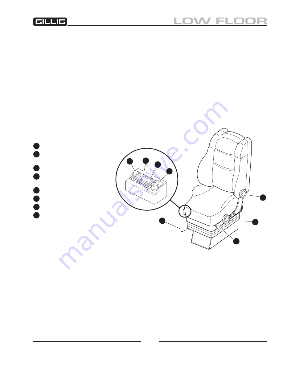
Refer to Figure 11-32, below. The following seat control listing covers the basic features of a typical
USSC seat. Options such as heaters and ventilators are not listed here.
A
Side bolster adjustor switch.
B
Upper lumbar back support
adjustment switch.
C
Lower lumbar back support switch.
D
Seat slide adjustment button
(optional).
E
Seat slide adjustment lever.
F
Seat height adjustment knob.
G
Seat tilt adjustment knob.
H
Seat back angle adjustment knob.
A
B
C
D
H
G
F
E
Figure 11-32, USSC Driver’s Seat Adjustments
Summary of Contents for LOW FLOOR
Page 18: ...Specifications 18...
Page 58: ...Preventive Maintenance 58...
Page 110: ...Engine 110...
Page 138: ...Transmission Driveline Rear Axle 138...
Page 182: ...Suspension 182...
Page 260: ...Air System 260...
Page 420: ...Electrical System 420 Deutsch DT Series Connectors...
Page 421: ...Electrical System 421...
Page 422: ...Electrical System 422 Deutsch HD 10 Series Connectors...
Page 423: ...Electrical System 423...
Page 424: ...Electrical System 424 Deutsch HD 30 Series Connectors...
Page 425: ...Electrical System 425...
Page 442: ...Heating Air Conditioning 442...
Page 492: ...Body and Interior 492 Figure 11 33 USSC Seat Assembly...
Page 493: ...Body and Interior 493 Figure 11 34 USSC Seat Suspension Assembly...
Page 495: ...Body and Interior 495 Figure 11 37 Seat Air Connections...


