Engine
94
Exhaust Clamp Installation
If your bus has aluminized steel band clamps installed, do not reuse
them. If you remove them, these clamps must be replaced with stainless
steel band clamps, available through your Gillig Parts representative.
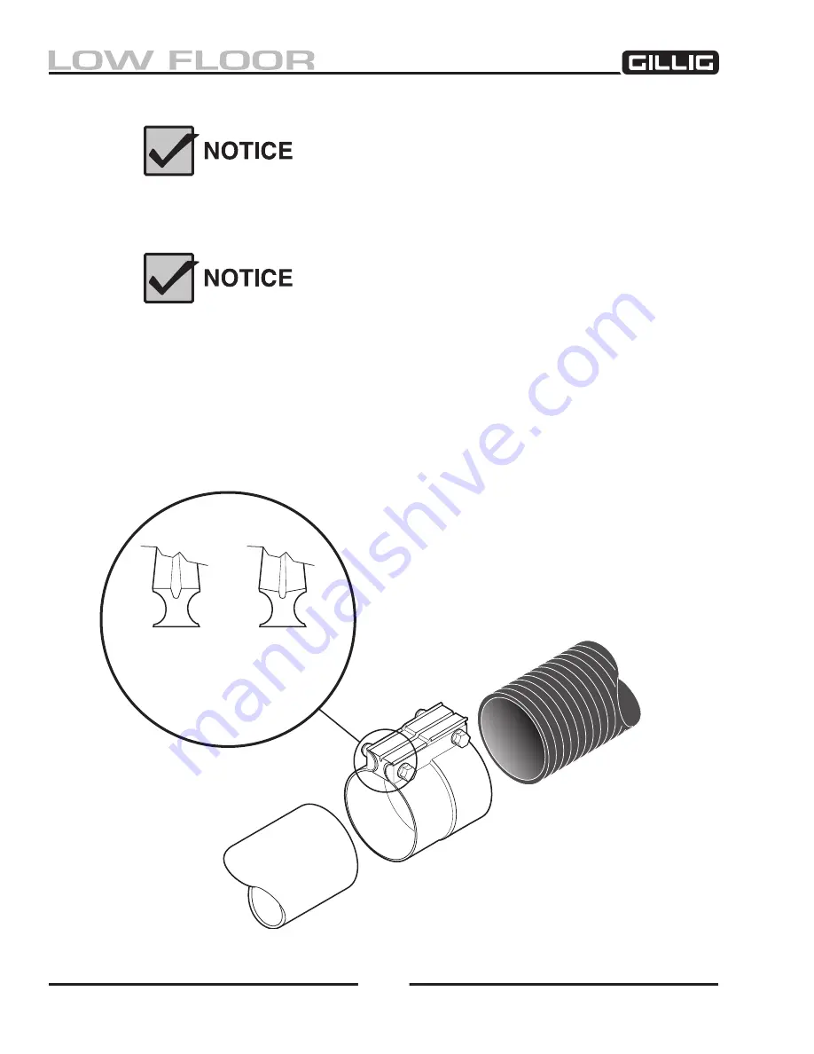
To achieve a proper seal, make sure that the step on the V-groove
installation indicator matches the step on the exhaust clamp.
1. Refer to Figure 3-13. Position the band clamp over the smallest tube. The larger end of the clamp
must be on the overlapping tube or flex.
2. Locate the step of the clamp to the overlapping tube at the joint.
3. Using the V-groove as a visual guide, alternately tighten bolts until the V-groove installation
indicator is approximately half closed (60 ft-lb / 81 N-m torque maximum).
Before
After
V-Groove
Installation
Indicator
Figure 3-13, Band Clamp
Summary of Contents for LOW FLOOR
Page 18: ...Specifications 18...
Page 58: ...Preventive Maintenance 58...
Page 110: ...Engine 110...
Page 138: ...Transmission Driveline Rear Axle 138...
Page 182: ...Suspension 182...
Page 260: ...Air System 260...
Page 420: ...Electrical System 420 Deutsch DT Series Connectors...
Page 421: ...Electrical System 421...
Page 422: ...Electrical System 422 Deutsch HD 10 Series Connectors...
Page 423: ...Electrical System 423...
Page 424: ...Electrical System 424 Deutsch HD 30 Series Connectors...
Page 425: ...Electrical System 425...
Page 442: ...Heating Air Conditioning 442...
Page 492: ...Body and Interior 492 Figure 11 33 USSC Seat Assembly...
Page 493: ...Body and Interior 493 Figure 11 34 USSC Seat Suspension Assembly...
Page 495: ...Body and Interior 495 Figure 11 37 Seat Air Connections...


