Brakes & Wheels
277
Automatic Brake Adjuster Checking Procedures
If the brake adjuster is not maintaining the proper applied stroke, before removing the brake adjuster,
check the condition of the foundation brake. If after inspecting the foundation brake no apparent prob-
lems are found, inspect the automatic brake adjuster to determine if it is operating properly. The inspec-
tion can be performed on or off the vehicle using the following procedures.
Block wheels to prevent vehicle from rolling.
Ensure system tank pressure is at 90-100 psi.
Check that push rod is fully retracted; apply air to release spring
brake.
If air is not available, spring brake must be manually caged back.
Do not use air tools on brake adjuster!
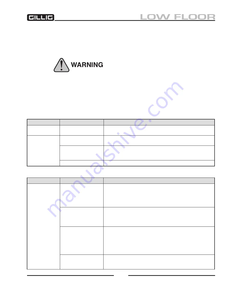
On Vehicle Inspection
Component
Cause
Action
Tight or dragging
brakes
Control arm mispositioned
Realign control arm and anchor bracket. Check “Installing Haldex
Automatic Slack Adjusters.”
Excessive chamber
push rod travel
Improper anchor bracket
connection to control arm
If anchor bracket to control arm connection is worn, loose, bent or
broken, it must be re-secured or replaced.
Low clutch torque
Rotate the 7/16" adjustment hex one full turn counterclockwise.
Replace brake adjuster if the torque is less than 13 ft-lb or no ratcheting
sound occurs.
Unknown
Perform automatic brake adjuster operational check (see below).
Off Vehicle Inspection
Component
Cause
Action
Adjuster not func-
tioning properly
Low clutch torque
Place adjuster arm in vise. Rotate the 7/16" adjustment hex counter
-
clockwise one full turn to check de-adjustment torque. After control arm
stops rotating, a minimum of 13 ft-lb will be required and a ratchet
-
ing sound will occur. Replace brake adjuster if the torque is less than
13 ft-lb or no de-adjustment ratcheting sound is present.
Control arm slippage
Place adjuster arm in vise. Rotate the control arm counterclockwise
until the control arm rotates to an INTERNAL STOP. If the installation
indicator goes past the indicator notch or does not stop rotating (arm
slips freely), replace the brake adjuster.
Unknown
If torque is above 13 ft-lb, scribe a line on the adjustment hex. Manually
pull the brake adjuster control arm clockwise then push back counter-
clockwise until the installation indicator stops in the indicator notch.
The hex will move in a clockwise direction when the control arm of the
brake adjuster is pushed back counterclockwise. Replace adjuster if hex
does not move.
Worn/missing control arm
wear bushing, and anchor
stud pin, if applicable
Remove and replace pin and bushings. If adjuster has passed the above
checks, re-install adjuster on vehicle, with new hardware.
•
•
•
•
•
Summary of Contents for LOW FLOOR
Page 18: ...Specifications 18...
Page 58: ...Preventive Maintenance 58...
Page 110: ...Engine 110...
Page 138: ...Transmission Driveline Rear Axle 138...
Page 182: ...Suspension 182...
Page 260: ...Air System 260...
Page 420: ...Electrical System 420 Deutsch DT Series Connectors...
Page 421: ...Electrical System 421...
Page 422: ...Electrical System 422 Deutsch HD 10 Series Connectors...
Page 423: ...Electrical System 423...
Page 424: ...Electrical System 424 Deutsch HD 30 Series Connectors...
Page 425: ...Electrical System 425...
Page 442: ...Heating Air Conditioning 442...
Page 492: ...Body and Interior 492 Figure 11 33 USSC Seat Assembly...
Page 493: ...Body and Interior 493 Figure 11 34 USSC Seat Suspension Assembly...
Page 495: ...Body and Interior 495 Figure 11 37 Seat Air Connections...


