Electrical System
383
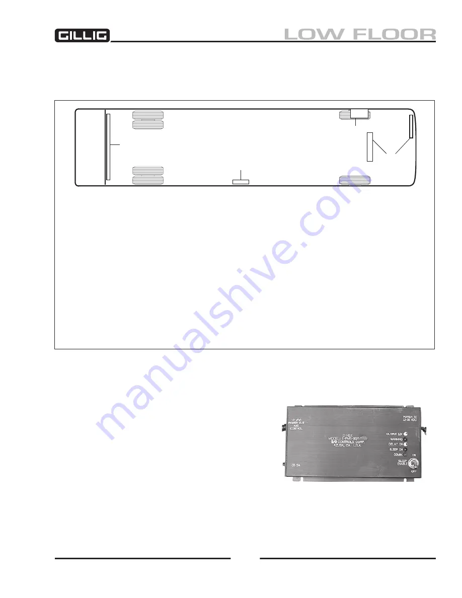
Figure 9-23, Multiplexer Component Locations
Multiplex System Components
The multiplexer modules are located in four or five locations inside the bus. Refer to Figure 9-
23 for a
diagram of these locations. The different types of modules are described below.
t-pms-0025* power management module
This module (Figure 9-
24
) is a switching power supply
circuit which takes a 10–36VDC input and converts it
to “clean” 12VDC power for the multiplex system. All
of the components in the multiplex system receive their
power from this module. A circuit breaker is installed on
the left side of the module. The “Sleep Enable” switch
should always be kept in the “ON” position. The Power
Management Module is located on the Rear Enclosure
Electrical Panel (see the “Electrical Panels”
section of this chapter for location).
Figure 9-24, Power Management Module
zone A & B:
Indicator Lamp Strip
(light bar)
and
Air Tank Compartment
.
Located at the top
of the driver’s windshield’s area, the Indicator Lamp Strip
B1
(ID’s #67 and #68) is a part of the
multiplexing network. Located on the ceiling behind the driver’s area in the Air Tank Compartment,
accessible by opening compartment door, are five multiplexer modules:
A1
(ID #64),
A2
(ID’s #65 and 66),
B2
(ID #69),
B3
(ID #70), and
B4
(ID #75).
zone C:
Exit Door.
A single module (on busses with rear exits) is installed in the area above the
rear exit door:
C1
(ID #71).
zone D:
Rear Enclosure Electrical Panel.
This panel is located behind a locking door at the
top of the rear bulkhead. Four multiplexer modules are located here:
D1
(ID #72),
D2
(ID #73),
D3
(ID #74), and
D4
(ID #76). The
Power Management Module
is also located here.
Radio Box.
Located above the left front wheel well, the radio box houses optional ITS (intelligent
transportation systems–GPS and voice annunciator) components:
B5
(ID #78).
zone D
zone C
Radio
Box
zone
A & B
Summary of Contents for LOW FLOOR
Page 18: ...Specifications 18...
Page 58: ...Preventive Maintenance 58...
Page 110: ...Engine 110...
Page 138: ...Transmission Driveline Rear Axle 138...
Page 182: ...Suspension 182...
Page 260: ...Air System 260...
Page 420: ...Electrical System 420 Deutsch DT Series Connectors...
Page 421: ...Electrical System 421...
Page 422: ...Electrical System 422 Deutsch HD 10 Series Connectors...
Page 423: ...Electrical System 423...
Page 424: ...Electrical System 424 Deutsch HD 30 Series Connectors...
Page 425: ...Electrical System 425...
Page 442: ...Heating Air Conditioning 442...
Page 492: ...Body and Interior 492 Figure 11 33 USSC Seat Assembly...
Page 493: ...Body and Interior 493 Figure 11 34 USSC Seat Suspension Assembly...
Page 495: ...Body and Interior 495 Figure 11 37 Seat Air Connections...


