Gilson Company, Inc.
Gilson Binder Ignition System: HM-378
Page 9
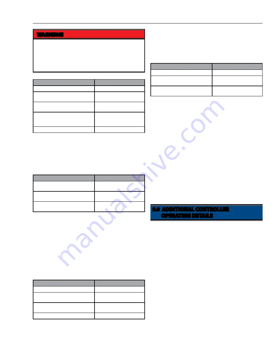
WARNING!
In custom programming mode, the programmer is
responsible for programming the door to be locked
during any segments where danger may exist by
opening the door. See other WARNINGS regarding
door lockout throughout this manual!
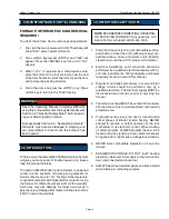
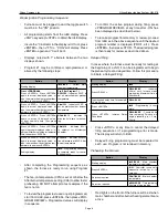
This is the start of the 2nd segment. Repeat program-
ming in the same sequence as above for 1st segment to
program additional segments 2, 3, and 4 if desired. If less
than 4 segments are used, after last Hold Time is keyed
and <ENTER> is pressed:
To review a program last used or just programmed, start
from
"IdLE", press <PROGRAM REVIEW> key. Program
values will display in sequence. The furnace is now ready
to run a Ramp-Hold program.
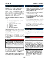
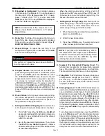
8.2 Delayed Firing Programming
If you wish to start the program at a delayed firing time,
it may be programmed for one-time use by adding the
following:
The furnace is now programmed to delay for 12 hours,
30 minutes from the time it is turned on until it starts the
Ramp-Hold program. Delay instructions are NOT retained
as part of the program and must be reset for each desired
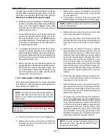
use. To start a program:
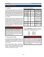
When
–On- is displayed, the controller runs a self-diag-
nostic routine for 5—10 seconds. Then a chamber tem-
perature display appears. The furnace will automatically
step though the four (or less) segments of rate ramps and
timed holds as programmed. If a delay was programmed,
the display shows time remaining, and
–On- activates at
00.00 time.
When a Ramp-Hold program is firing, it is possible to
skip to the next segment at any time by pressing <CON-
TINUE>.
SKIP will display momentarily followed by
the
RA# display of the next segment. Press <ENTER>
immediately to skip to the next segment. If <ENTER> is
not pressed, the original segment resumes. At the end
of the program, the furnace will shut off and the display
will show
CPLT.
A. Operation: The first time the furnace is powered, the
HM-378 controller will display
IdLE and the alarm will
sound briefly. The controller will self-test for a period
of 10—15 seconds and the display will alternately
display
IdLE and the Main Chamber temperature.
B. Programming: Programming begins from IdLE. If
the display shows FAIL or TC2 instead of
IdLE, the
thermocouple is probably either disconnected or
burned out.
C. Time & Temperature Display: During time display,
a centered display period appears (
XX.XX). During
temperature display, the period disappears. The cen-
tered display period separates hours from minutes
(i.e. 1 hour and 30 minutes displays as
01.30). Up to
99 hours and 99 minutes can be entered, displayed
as
99.99. Thus it is important to note that more than
one hour can be entered in minutes only. The integers
after the decimal are NOT hundredths of hours.
Action
Display
Starting display.
IdLE
Press <RAMP-HOLD>.
RA 1/XXXX - Indicating °C per
hour ramp rate for segment 1.
Press <ENTER> (or new value, then
<ENTER> 9999°C/hour maximum.
C1/XXXX - Indicating °C final
temperature for segment 1.
Press <ENTER> (or new terminal tem-
perature at end of ramp, then <EN-
TER>.
Hd/XX.XX - Indicating Hours
Minutes Hold time for final tem-
perature of segment 1.
Press <ENTER> (or new hold time).
RA 2
Action
Display
Starting display.
IdLE
Press <DELAY>.
DELA/XXXX - Max. time 99.95
hours minutes.
Input desired delay time, for example:
12 hrs, 30 min.
DELA/12.30
Press <ENTER>.
IdLE
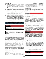
Action
Display
Press <ENTER> (or new Afterburner
temperature).
CAb/XXXX - Indicating After-
burner temperature, °C.
Press <ENTER> (or new Fan-On tem-
perature, 1,820°C is maximum).
CFN/XXXX - Indicating Fan-
On temperature setting, °C.
Press <ENTER>.
IdLE/XXXX - Indicating Main
Chamber temperature.
Action
Display
Starting display.
IdLE
Press <ENTER>.
-On- then XXXX - Temperature
of main chamber.
Press <ENTER>.
XX.XX - Time remaining in de-
lay program.
9.0 ADDITIONAL CONTROLLER
OPERATING DETAILS


