6
De
cr
ea
se
In
cr
ea
se
+
ALLUMINI OXIDE CAPSULE
PRODUCT NO: IM-CAP-003
LOT NO: 20050219
Before You Begin
• Read all these instructions prior to operation.
• Carefully remove the system from the shipping box and foam packing.
• Remove the plastic covering and place machine on a hard flat surface.
• Unpack the Crystal Capsule
™
, handpiece and tubing.
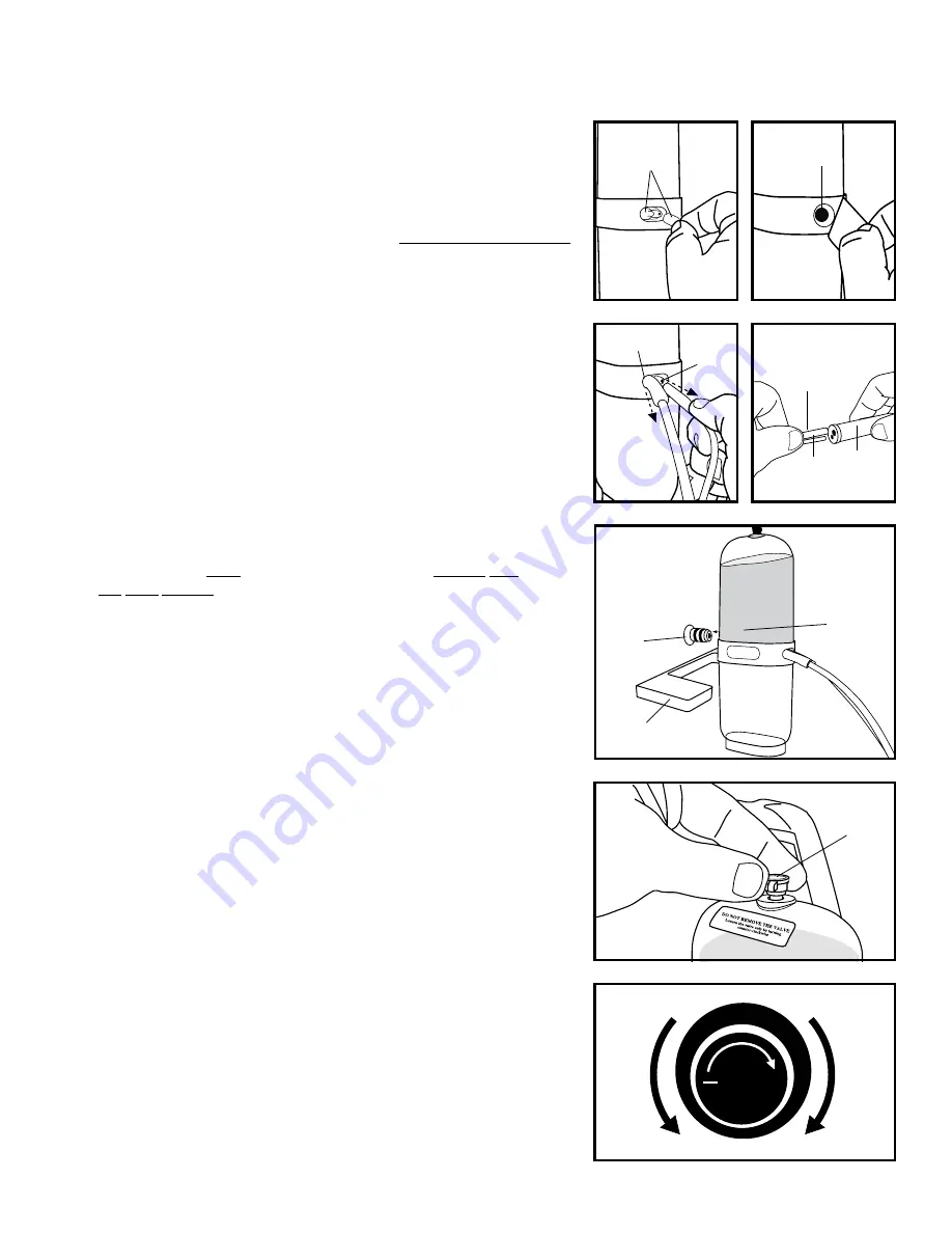
• Remove the 2 rubber caps from the port posts. Do not discard rubber caps.
You will need the rubber caps to plug the port posts when disposing of used
capsule (fig. 4).
• Hold capsule upright. Remove the label covering vacuum hole (fig. 5).
Attaching the Tubing & Nozzle
• Connect the proper size tubing to the appropriate post on the capsule. Push
tubing firmly onto the posts (fig. 6).
• Connect the proper size tubing to the flat end of the nozzle. Push tubing firmly
into the nozzle (fig. 7).
Attaching the Media Canister
• Slide the Crystal Capsule’s
™
opening onto the male vacuum port post sticking
out of the front of your Gio Peel. Vacuum port post is located between the
Crystal Capsule
™
stabilizer (fig. 8).
•
Wipe post clean
prior
to inserting. Be sure you slide
straight
onto
the post.
DO
NOT
TWIST
or you will damage the
sealing o-rings
.
• Insert capsule fully onto the post with both o-rings down inside the opening
in the capsule.
Turning the Unit On
• Place the master power switch on the side of the unit in the
OFF
position.
• Plug the
POWER CORD
into the connector located on the back of the
microdermabrader.
• Attach the other end of the
POWER CORD
to a properly grounded outlet
supplying 115vac.
• Depress the I portion of the master power switch located on the back of the
Gio Peel to turn the unit on. The fan will start.
• Depress the I portion of the power switch located on the front of the Gio Peel
to turn the suction on.
Adjusting Crystal Flow
• Unscrewing the nut counter-clockwise adjusts crystal flow. You should notice
some movement, or bubbling, of the new abrading media inside the Crystal
Capsule
™
when preforming procedures (fig. 9).
• If less crystal flow is desired, unscrew the nut until you see a slight decrease of
the crystal bubbling inside the capsule, or no movement at all which indicates
minimum volume of crystal flow (fig. 9).
Vacuum Control Valve
• Turn the Vacuum Control Valve clockwise to increase the vacuum or counter-
clockwise to decrease vacuum (fig. 10).
INSTALLATION & SET UP
Contact us if the unit fails to operate during these steps.
Figure 4
Figure 5
Figure 6
Figure 7
Figure 8
Figure 9
Figure 10
Vacuum
Port
&
Sealing
O-Rings
Insert
Capsule
STRAIGHT
onto
Vacuum
Post
Rubber Caps
Vacuum Hole
Large
Tube
Small
Tube
Large Tube
Small
Tube
Nozzle
Capsule
Nut
Crystal Capsule
™
Stabilizer


