6
7
OperatOr, safety, and general maintenance manual:
giO electric bicycles, scOOter type e-bikes and 3 wheeler
5.2 Adjusting the brakes: (Applicable to all electric bicycles)
NOTE:
depending on the model of electric bicycle you have and the type of braking
system on it, brake adjustments can be made in a combination of any of 4 different
methods. refer to figure C, then adjust both brake cables so that the distance “l”
referred to, is half that when brakes are fully applied.
1)
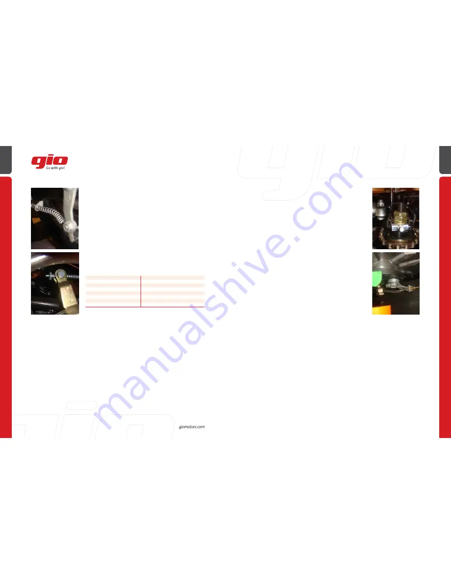
Electric bicycle type models have a basic adjustment at the end of the cable
where it goes into the handlebar lever. Simply loosen the locknut and rotate the
adjuster in or out until you acquire the correct lever specification as pictured in
figure C, to half distance “l”. Then retighten the locknut, usually finger tight. major
adjustments are similar to 5.2.2) below.
2)
most 350 watt models have a cable clamp at the end of the cable where it
connects to the brake actuator arm on the brake hub, and this is where you would
make a major adjustment. Being careful not to damage the cable, hold the end of
it with some form of pliers and then loosen the nut on the cable clamp. But please
note that the actuator arm is spring loaded and the cable will slip once loosened,
so you may need an assistant. you will now be able to adjust the cable length
accordingly. Then carefully retighten the cable clamp nut. Several attempts may
be necessary to get it right, but once this is done, the finer adjustments should be
made at the other end of the cable as referred to in 5.2-1) above.
parts name
Moment
handlebar
18NM
Front stem
18NM
saddle
18NM
saddle stern
18NM
Front wheel axes
18NM
rear wheel axes
30NM
Middle wheel bolt
30NM
3)
most 500 watt models have an adjuster nut on the threaded end of the cable
where it goes into the brake actuator arm at the brake hub. Tighten or loosen as
necessary. It has detents to make it easy to adjust, and the spring tension will keep
it from rotating loose, so it usually would not require a locknut. 4) Certain models
have three adjustment screws on the outer edge of the rear brake hub. loosen
the locknuts on all three screws and then use the throttle to slowly spin the wheel
and adjust the screws until the brakes can be heard dragging. Then back them off
slightly so that they are no longer heard dragging and retighten the locknuts. make
sure they are all evenly balanced.
NOTE:
It is normal for the brakes to wear as they are being used, so frequent
adjustments are required.
remember: how fast you can stop is far more important than how fast you can go!
5.3 Adjusting the handlebar on an electric bicycle:
In order to correctly position the handlebar, loosen the stem bolt enough so that
the stem will be able to rotate and move up or down. Then stand in front of the
handlebar with the front wheel clamped between your legs and adjust it to the
desired height for the intended rider, making sure that the stem is not raised
past the safety line marked upon it. is properly centered (perpendicular to the
wheel when viewed from overhead) and retighten adequately. Now you should
set the handlebar rotational angle by loosening the handlebar clamp bolt, rotate
the handlebars to the desired position and retighten the clamp bolt. Then make
sure the brake levers are all the way out to the grips and at a comfortable angle to
operate, set them according to specifications in figure C, and tighten securely.
NOTE:
These are all extremely important safety items! If in doubt, please consult
your dealer.
5.4 Adjusting the handlebar on a scooter type e-bike
a)
handlebars and grips usually come preset from the factory, but both handle
grips are adjustable axially, so only minor rotational adjustments may be required.
Simply loosen the Phillips or Allen-head cap screws slightly, rotate handle grips to
a comfortable position, retighten, and readjust the mirrors.
NOTE: Both handle grips and mounts should always be tight, and slid all the way
on to the handlebar.
b)
for any other adjustments see a dealer or consult service manual.
5.5 Changing front tire and flat repair:
NOTE:
Please note the relative orientation of all washers, spacers, or adjustment
plates as you loosen the main axle nuts. Changing the tire or inner tube is the
same for front and rear tires.
a)
r & r front wheel according to Chapter 3 or 4, step 1, as applicable.
b)
remove the valve from the valve stem with valve removal tool, to allow all the
air out of the tube.
c)
“Break the bead” by pressing the tire away from the rim. Being careful not to
scratch the rim, pry the tire bead over the rim beginning with the side opposite
the valve stem. you may need to use tire lever tools for this task.
d)
Pull the inner tube out of the tire, then replace. Tire too, if required, being
careful not to pinch the inner tube and be sure that you install the replacement
tire according to the rotational direction arrow on the sidewall. reinflate and
maintain at correct pressure as listed on sidewall.


