background image

Heat pump water heater 


- 41 - 

EN 

5.5


Anode verification 

(periodic) 


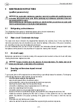
The equipment is protected against corrosion by a glass porcelain lining on the inner surface. The equipment is also 
fitted with a magnesium anode protecting it against the effect of the eddy currents that might damage it: its life 
depends on how it is operated and on the water quality. 
The anode is installed on the 5-hole counterflange. 
To check its status you need to: 


cut off the power supply to the equipment


empty the tank (please refer to the relevant section); 


using a screwdriver, remove the cap protecting the electrical components; 


disconnect the electric cables from the relevant terminals; 


uninstall the counterflange using an appropriate wrench for M10 nuts; 


extract the counterflange from its housing; 


descale it and remove any limestone deposits, paying attention not to damage the resistance shell; 


reinstall the resistance, tightening the M10 nuts to a torque of 12 Nm; tighten the nuts in a cross-shaped 
pattern. Pay attention to the proper positioning of the gasket and of the screws on which the nuts are 
tightened; 


fill the tank and verify that there are no leaks; 


restore the electrical connections and reinstall the cap protecting the electrical components.  

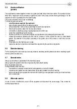
5.6


Outside cleaning 

For the cleaning of the outer shell only use soapy solutions, absolutely avoiding abrasive products containing organic 
thinners (alcohol, benzine, etc.) 

5.7


General notes 

Always use tools that are appropriate for the intended purpose. 
Always replace the gaskets and/or the o-rings ensuring the hydraulic sealing. 
Only use genuine spare parts. 
During reinstalling make sure that: 


the resistance is properly housed and the sealing gaskets are correctly installed; 


the safety and regulation devices (thermostats) are properly installed inside their housings; 


before reconnecting the equipment to the mains fill it (referring to the appropriate section) and check that there 
are no water leaks. 

5.8


After-sale service 

In case of errors or malfunctions, switch off the equipment and disconnect the power supply. Then contact the 
technical support service. 

Summary of Contents for Futura 100 TS

Page 1: ...9 2014 FUTURA 100 TS SCALDACQUA A POMPA DI CALORE CON SERPENTINO SOLARE Istruzioni per l installazione l uso e la manutenzione HEAT PUMP WATER HEATER WITH SOLAR COIL Instruction for installation use and maintenance IT EN ...

Page 2: ... 2 ...

Page 3: ...resente manuale si riferiscono al livello tecnologico attuale Si prega di consultare sempre le istruzioni contenute nel presente manuale al momento dell installazione Le attività descritte in queste istruzioni esigono conoscenze specialistiche corrispondenti ad una completa e comprovata formazione professionale nel settore dell installazione di impianti Di conseguenza si consiglia di eseguire le o...

Page 4: ...9 2 4 1 SERBATOIO 9 2 4 2 GRUPPO FRIGORIFERO 9 2 4 3 RESISTENZA PER SCALDARE L ARIA 9 2 4 4 PROTEZIONE ANTICORROSIONE 10 2 4 5 ISOLAMENTO TERMICO E RIVESTIMENTO 10 2 5 CARATTERISTICHE DIMENSIONALI 10 2 6 TABELLA DATI TECNICI 11 3 INSTALLAZIONE E PRIMA MESSA IN SERVIZIO 12 3 1 FISSAGGIO A MURO 12 3 2 COLLEGAMENTO IDRAULICO 12 3 2 1 GRUPPO DI SICUREZZA IDRAULICO 13 3 2 2 RIDUTTORE DI PRESSIONE 13 3 ...

Page 5: ...GNALAZIONE ERRORI 17 4 4 VERIFICA EFFICIENZA GRUPPO DI SICUREZZA IDRAULICO 17 4 5 SVUOTAMENTO DELL APPARECCHIO 17 5 NORME DI MANUTENZIONE 18 5 1 MANUTENZIONE GRUPPO FRIGORIFERO 18 5 2 CIRCUITO DELL ACQUA SCARICO CONDENSA 18 5 3 ALIMENTAZIONE CIRCUITO DELL ARIA 18 5 4 DISINCROSTAZIONE E PULIZIA DEL CALCARE 18 5 5 VERIFICA ANODO 19 5 6 PULIZIA ESTERNA 19 5 7 NOTE GENERALI 19 5 8 SERVIZIO POST VENDIT...

Page 6: ...nylon forniti di serie siamo montati correttamente il gruppo di sicurezza idraulico sia correttamente installato non sia manomesso e sia efficiente l installazione e la manutenzione sia effettuata da personale qualificato nel rispetto delle normative vigenti prima di iniziare gli interventi di manutenzione o riparazione su componenti che contengono liquido refrigerante quest ultimo deve essere rim...

Page 7: ...di calore deve essere conservato e trasportato nell imballo originale in senso verticale diritto Per brevi tratti è consentita una posizione inclinata di 45 qualora si presti la massima cautela nel trasporto A causa dell inclinazione in avanti nell utilizzare carrelli elevatori o altri mezzi di trasporto procedere a velocità ridotta e fissare l apparecchio per impedirne il ribaltamento Dopo il tra...

Page 8: ...iene sottoposto ad espansione a bassa pressione dilatazione e ritornato nell evaporatore può di nuovo prelevare calore dall ambiente circostante La pompa di calore per acqua calda funziona a una temperatura ambiente compresa fra 8 C e 32 C La pompa di calore per acqua calda è un apparecchio già pronto per essere collegato che serve a riscaldare acqua potabile ed è fondamentalmente costituito da se...

Page 9: ...a calda Attraverso l utilizzo di energie rinnovabili e di un ottimale efficienza energetica con la pompa di calore per acqua sanitaria si rende possibile e sensato un riscaldamento dell acqua ecocompatibile e conveniente per tutto l anno 2 4 Componenti principali 2 4 1 Serbatoio Il serbatoio è costituito da una caldaia interna cilindrica stagna ed è realizzato in conformità alla norma DIN 4753 Par...

Page 10: ...o un anodo in magnesio 2 4 5 Isolamento termico e rivestimento L isolamento termico è realizzato in poliuretano espanso rigido PUR privo di CFC altamente biologico Grazie al completo rivestimento in materiale espanso compresso si ottengono minime perdite energetiche Il rivestimento esterno è costituito da un mantello in lamiera verniciata bianca 2 5 Caratteristiche dimensionali Le caratteristiche ...

Page 11: ...ante R134a Quantità di fluido refrigerante kg 280 Potenza massima assorbita W 2400 Elemento riscaldante Acqua Potenza elettrica W 1200 Temperatura massima acqua con resistenza C 65 Elemento riscaldante Aria Potenza elettrica W 900 Alimentazione elettrica Tensione potenza massima assorbita V W 230 2400 Frequenza Hz 50 Grado di protezione IPX2 Lato aria Portata d aria m3 h 80 Volume minimo del local...

Page 12: ...rata non deve essere 8 C e 32 C Utilizzare determinati locali per sfruttare il calore in eccesso prodotto da asciugabiancheria frigoriferi congelatori ecc L aria non deve essere eccessivamente depurata né troppo contaminata di polvere Deve essere presente uno scarico delle acque nere con sifone per eliminare la condensa L aria più fredda espulsa consente di ridurre la temperatura ambiente di ca 2 ...

Page 13: ... lasciato aperta all atmosfera Un tubo di scarico deve essere previsto in pendenza continua verso il basso ed in un luogo privo di condensa e ghiaccio La tubazione non deve presentare nessuna ostruzioni per evitare sovrapressioni 3 2 2 Riduttore di pressione Nel caso esistesse una pressione di rete superiore a 0 5 MPa 5 bar è necessario applicare un adeguato riduttore di pressione Fig 3 rif 4 posi...

Page 14: ...abbrica ed è provvisto di spina per il collegamento di una presa con adeguate caratteristiche elettriche Verificare che la tensione di rete sia conforme al valore riportato sulla targhetta applicata all apparecchio e che la rete elettrica possa fornire la potenza indicata Per l esclusione dell apparecchio dalla rete deve essere utilizzato un interruttore bipolare rispondente alle norme EN apertura...

Page 15: ...tenza integrativa per l aria Il pannello di controllo semplice e razionale è costituito da quattro tasti di comando per la gestione delle diverse funzioni 4 3 1 Funzionamento Standard senza nessun comando attivato Sul display appare la temperatura del serbatoio L acqua viene portata alla temperatura di 56 C tramite la pompa di calore La ventola di raffreddamento si accende quando la pompa di calor...

Page 16: ...fort e Riscaldamento aria non possono essere attivate contemporaneamente si escludono a vicenda 4 3 6 Accensione Spegnimento scaldacqua Quando lo scaldacqua è spento sul display appaiono due punti In condizioni normali di funzionamento per accendere lo scaldacqua bisogna premere il pulsante di attivazione della funzione vasca fino all accensione del display indicatore di temperatura In condizioni ...

Page 17: ...are un reset del sistema premere contemporaneamente i tasti Comfort e Vasca 4 4 Verifica efficienza gruppo di sicurezza idraulico L efficienza del gruppo idraulico è molto importante per evitare sovrapressioni interne al serbatoio danneggiandolo e consente un uso in sicurezza dell apparecchio per l utente Verificare periodicamente secondo le indicazioni del costruttore del gruppo di sicurezza idra...

Page 18: ...fettuandone la pulizia all occorrenza 5 3 Alimentazione circuito dell aria Gli interventi di manutenzione si limitano ad effettuare all occorrenza o a fine turno una pulizia dell evaporatore in concomitanza con il controllo degli anodi di protezione in magnesio AVVERTENZA Pericolo di lesioni a causa di alette a spigoli vivi Le alette non devono essere deformate o danneggiate alette a pettine del c...

Page 19: ...a di serraggio pari a 12 Nxm eseguire tale operazione seguendo uno schema di avvitamento a croce Fare attenzione al corretto posizionamento della guarnizione e delle viti su cui sono serrati i dadi riempire il serbatoio e verificare che non ci siano perdite ripristinare i collegamenti elettrici e rimontare la calottina proteggi parti elettriche 5 6 Pulizia esterna Per la pulizia del mantello ester...

Page 20: ...lla salute Il riciclo dei materiali consente di preservare le risorse naturali Per ulteriori informazioni sul riciclaggio di questo prodotto contattare gli uffici del comune di appartenenza il servizio per lo smaltimento dei rifiuti domestici o il rivenditore installatore presso il quale è stato acquistato il prodotto Il non rispetto di tali modalità di smaltimento prevede sanzioni così come previ...

Page 21: ...e termica dell acqua in riscaldamento Per evitare il gocciolamento installare un vaso di espansione o collegare la valvola di sicurezza ad uno scarico Vedi sezione relativa Gocciolamento gruppo di sicurezza idraulico e Vaso d espansione Perdite d acqua NOTE GENERALI Generalmente le perdite si notano nella parte bassa dell apparecchio Verificare le perdite sempre nelle ZONE DI ORIGINE indicate di s...

Page 22: ...Scaldacqua a pompa di calore 22 IT 8 Illustrazioni Fig 1 Fig 2 Distanze da ogni tipo di superficie ...

Page 23: ...Scaldacqua a pompa di calore 23 IT Fig 3 Fig 4 ...

Page 24: ...Scaldacqua a pompa di calore 24 IT ...

Page 25: ...his manual refer to the current technological level Please always refer to the instructions contained in this manual when installing the equipment The operations described in these instructions require specialised knowledge achievable through a comprehensive and proven professional training in system installation As a consequence we recommend that you only perform the installation operations descr...

Page 26: ...ES 31 2 4 MAIN COMPONENTS 31 2 4 1 TANK 31 2 4 2 REFRIGERATING UNIT 31 2 4 3 HAIR HEATING RESISTANCE 31 2 4 4 ANTI CORROSION PROTECTION 31 2 4 5 THERMAL INSULATION AND COATING 32 2 5 DIMENSIONAL CHARACTERISTICS 32 2 6 TECHNICAL DATA TABLE 33 3 INSTALLATION AND FIRST START UP 34 3 1 WALL INSTALLATION 34 3 2 HYDRAULIC CONNECTION 34 3 2 1 HYDRAULIC SAFETY UNIT 35 3 2 2 PRESSURE REDUCER 35 3 2 3 EXPAN...

Page 27: ...9 4 3 9 ERROR NOTIFICATION 39 4 4 HYDRAULIC SAFETY UNIT EFFICIENCY CHECK 39 4 5 UNIT EMPTYING 39 5 MAINTENANCE INSTRUCTIONS 40 5 1 REFRIGERATING UNIT MAINTENANCE 40 5 2 WATER CIRCUIT CONDENSATE DISCHARGE 40 5 3 AIR CIRCUIT SUPPLY 40 5 4 DESCALING AND LIMESTONE DEPOSIT REMOVAL 40 5 5 ANODE VERIFICATION 41 5 6 OUTSIDE CLEANING 41 5 7 GENERAL NOTES 41 5 8 AFTER SALE SERVICE 41 6 DIAGRAM AND FIGURE LI...

Page 28: ...perly installed the hydraulic safety unit must be properly installed intact and in good working order installation and maintenance must be performed by qualified personnel in compliance with the regulations in force before starting any maintenance or repair operations on components containing any cooling fluid a qualified technician must remove an appropriate amount of the latter to ensure the ris...

Page 29: ... and transporting it always keep the heat pump water heater vertical straight in its original packaging For short stretches it can be inclined by 45 provided utmost care is taken when transporting it Due to the forward inclination when using forklift trucks or other means of transport proceed slowly and fasten the equipment to prevent it from tipping After transporting the equipment in inclined po...

Page 30: ...ion and after returning to the evaporator it can again draw heat from the surrounding environment The hot water heat pump operates at ambient temperatures ranging between 8 C and 32 C The hot water heat pump is a connection ready equipment whose function is heating drinkable water it basically consists of the water tank and of the coolant air and water circuit components as well as of all the cont...

Page 31: ... is manufactured in compliance with the DIN 4753 standard Part 3 2 4 2 Refrigerating unit The refrigerating circuit is located in the upper section of the water heater and consist of Refrigerant fluid R134a Rotary compressor Thermostatic expansion valve Combined filter drier and collector of the refrigerating circuit High power blade evaporator Electronic axial fan Average sized Cu cooling pipes H...

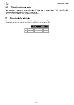
Page 32: ... The full compressed foam coating allows to minimise energy losses The outer coating consists of a white painted metal sheet shell 2 5 Dimensional characteristics The technical and dimensional characteristics of the equipment are indicated in Fig 1 The electrical characteristic data of each model can be found on the equipment itself Unit HP100 A mm 1415 B mm 605 ...

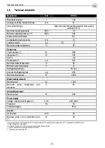
Page 33: ...C 10 Refrigerating fluid type R134a Amount of refrigerating fluid kg 280 Maximum input power W 2400 Water heating element Electric power W 1200 Maximum water temperature with resistance C 65 Air heating element Electric power W 900 Power supply Voltage maximum input power V W 230 2400 Frequency Hz 50 Protection degree IPX2 Air side Air flow rate m3 h 80 Minimum volume of the installation room m3 2...

Page 34: ...perature or the temperature of the input air must range between 8 C and 32 C If possible install the equipment in a room allowing to exploit the excess heat generated by tumble driers refrigerators freezers etc Air must be neither excessively purified nor too contaminated with dust There must be a black water drain with a syphon to eliminate condensation The cooler output air allows to reduce the ...

Page 35: ...2 2 Pressure reducer Should the network pressure exceed 0 5 MPa 5 bar you need to install an appropriate pressure reducer Fig 3 ref 4 upstream of the hydraulic safety unit ensuring the indicated operating range please refer to the technical data table 3 2 3 Expansion tank To prevent any overpressures that might damage the equipment frequently triggering the safety unit and causing water dripping i...

Page 36: ...alue specified in the label applied on the equipment and that the mains can supply the specified power To disconnect the equipment from the mains you need to use a two pole switch complying with the EN standards contact opening 3mm preferably equipped with fuses The connection must be established by inserting the plug into the appropriate outlet that must comply with the regulations in force WARNI...

Page 37: ... management of the temperature and of the complementary air resistance The control panel simple and rational consists of four control buttons for the management of the different functions 4 3 1 Standard operation without any activated control The tank temperature appears on the display Water is brought to the temperature of 56 C by the heat pump The cooling fan goes on when the heat pump is on and...

Page 38: ...at the same time they are mutually exclusive 4 3 6 Water heater switch on switch off When the water heater is off two dots appear on the display Under normal operating conditions to switch on the water heater you need to press the tank function enabling button until the temperature indicator display goes on Under normal operating conditions to switch off the water heater you need to hold the tank ...

Page 39: ... For the Technician to reset the system press the Comfort and Tank buttons at the same time 4 4 Hydraulic safety unit efficiency check The hydraulic unit efficiency is very important to prevent any overpressures inside the tank that would damage it and allows the user to safely operate the equipment Periodically check the efficiency of the hydraulic safety unit according to the instructions provid...

Page 40: ...upply Maintenance operations only include the cleaning of the evaporator when needed or at the end of each shift when checking the protective magnesium anodes WARNING Danger of injuries due to the presence of sharp edge blades The blades must not be deformed or damaged comb blades of the condenser 5 4 Descaling and limestone deposit removal periodic To get a good yield out of the equipment we reco...

Page 41: ...hten the nuts in a cross shaped pattern Pay attention to the proper positioning of the gasket and of the screws on which the nuts are tightened fill the tank and verify that there are no leaks restore the electrical connections and reinstall the cap protecting the electrical components 5 6 Outside cleaning For the cleaning of the outer shell only use soapy solutions absolutely avoiding abrasive pr...

Page 42: ...s for the environment Recycling of materials helps to preserve natural resources For further information about the recycling of this appliance please contact your municipal offices your domestic waste disposal service or the retailer installer from whom the appliance was purchased The penalties for failure to comply with these disposal procedures are laid down in local legislation WARNING the equi...

Page 43: ...the thermal expansion of the heating water To prevent the dripping install an expansion tank or connect the safety valve to a drain Please refer to the sections Water dripping from the hydraulic safety unit and Expansion tank Water leaks GENERAL NOTES Leaks generally occur in the bottom section of the equipment Always check for leaks in the SOURCE AREAS specified below Condensation If the water in...

Page 44: ...Heat pump water heater 44 EN 8 Illustrations Fig 1 Fig 2 Distances from any surface ...

Page 45: ...Heat pump water heater 45 EN Fig 3 Fig 4 ...

Page 46: ... 46 APPUNTI NOTES ...

Page 47: ... 47 ...

Page 48: ...scritos en el siguiente manual satisfacen los requisitos esenciales establecidos por las siguientes directivas europeas BT 2006 95 CE EMC 2004 108 CE PED art 3 3 97 23 CE Il Responsabile The Manager Der Verantwortliche Le Responsable El Responsable Marco GIONA La ditta declina ogni responsabilità per eventuali inesattezze contenute nelle presenti istruzioni dovute a errori di stampa o trascrizione...

Reviews: