background image

Pag.  18

OPERATING INSTRUCTIONS  

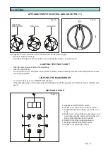
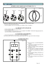
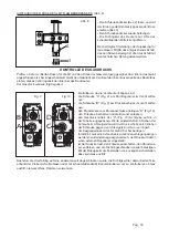
  Set temperature and use switch E to increase and switch D to decrease temperature.  

  Press switch A for a few seconds until pilot light B above it comes on to override pre-heating function F and go 

directly to the set temperature.  

  The display always shows the current temperature value. To find out the set temperature, just press key E. 

When the set temperature is reached, an acoustic signal will indicate ‘appliance ready’.   

  In order to carry out ‘MELT’ pre-heating, press A and keep F pressed for a few seconds until red light G above 

the switch comes on. In this status the fryer works intermittently until the temperature of 100°C is reached.

The fryer automatically comes on again when the temperature falls below a set level, so that the oil is maintained 

in pre-heating status. If you need to heat the oil to the set frying temperature, just keep switch F pressed for a 

few minutes until luminous light G goes off. The appliance will then automatically reheat the oil if it falls below the 

required temperature.  

TURNING OFF THE MAIN BURNER

-  Press switch A  (STOP).

-  Turn the knob (Fig. 12) back position “0”.

-  Turn the knob (Fig. 11) back to the ‘SWITCH-ON’ position. 

TOTAL SHUTDOWN

-  Turn the knob to ‘EVERYTHING SWITCHED OFF’ position and turn off the gas stopcock behind the applian-

ce.  

-  Switch off the circuit breaker.

-  Place the lid on the frying compartement/frying compartements.

DRAINING THE OIL

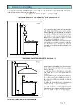
In order to drain the basin of the used oil, allow the oil to cool, open the fryer’s door, fit the oil collection basin with 

the relevant filter, if it has not already been inserted, and open the drain cock. The oil is discharged through the 

cock and the basin empties. To keep the oil at its best, it is advisable to leave it in a cool place once it has been 

filtered.

Summary of Contents for 921PGC

Page 1: ...S APPLIANCES WITH MELTING DEVICES MANUEL D INSTRUCTIONS POUR L UTILISA TION ET L ENTRETIEN DES FRITEUSES SUR MEUBLE A GAZ AVEC DISPOSITIF MELTING GEBRAUCHS UND WARTUNGSANLEITUNG FÜR TISCH GAS FRITEUSEN MIT MELTING VORRICHTUNG MANUAL DE INSTRUCCIONES PARA EL USO Y EL MANTENIMIENTO DE LAS FREIDORAS SO BRE MUEBLE DE GAS CON DISPOSITIVO MEL TING REV 00 2008 COD ZSL2513 ...

Page 2: ...arne l integrità e sistemarlo nel luogo d utilizza zione Procedere alla messa in piano e alla regola zione in altezza agendo sui piedini livellatori come indicato in Fig 1 Se l apparecchiatura viene posizionata con tro una parete quest ultima deve resistere a valori di temperatura di 80 C e se è infiam mabile è indispensabile l applicazione di un isolante termico Togliere dai pannelli esterni la pe...

Page 3: ...he l evacuazione dei fumi non venga ostacolata da ostruzioni e o da eccessiva lunghezza del tubo di scarico lunghezza massima 3m COLLEGAMENTO SOTTO CAPPA ASPIRANTE Quando l apparecchio viene installato sotto cappa aspirante bisogna verificare che ven gano rispettate le seguenti indicazioni Il volume aspirato deve essere superiore a quello dei gas combusti generati vedere la normativa in vigore L al...

Page 4: ...seguito Legge n 1083 del 06 12 71 norme per la sicurezza dell impiego del gas combustibile Norme UNI CIG7129 72 e UNI CIG7131 72 norme per impianti a gas alimentati dalla rete di distribuzione o gas GPL Circolare del ministero dell interno n 68 del 25 11 1969 e sue varianti norme di sicurezza per impianti termici a gas di rete Lettera circolare n 412 4183 DEL 06 02 1975 norme di sicurezza per impi...

Page 5: ... rete del gas è necessario controllare che non vi siano fughe nei giunti e nei raccordi A questo scopo usare dell acqua saponata o un prodotto schiumogeno specifico per l individuazione delle perdite NON USARE MAI FIAMMIFERI ACCESI S A G I D I P I T r a b m N I E N O I S S E R P M O N N I M X A M 0 2 G O N A T E M S A G 0 2 7 1 5 2 1 3 0 3 G L P G 7 3 0 3 8 2 5 2 0 2 5 4 5 3 CONTROLLO DELLA PRESSIO...

Page 6: ...9 sulla presa di pressione nella val vola applicare il manometro alla presa di pressione D Fig 10 accendere la friggitrice e far partire i bruciatori regolare la pressione del gas ai valori indicati nella tabella agendo sulla vite C Fig 10 ricordando che girando la vite in senso orario si aumenta la pressione e in senso antiorario si diminuisce la pressione in uscita dalla valvola per il G20 deve ...

Page 7: ... riportato nella normativa in vigore Prima di consegnare l apparecchio all utente è necessario verificare che funzioni correttamente comunicare all utente le istruzioni per l uso 2 ISTRUZIONI D USO L apparecchiatura dovrà essere destinata solo all uso per la quale è stata espressamente concepita Ogni altro uso è da ritenersi improprio Durante il funzionamento sorvegliare l apparecchiatura 2 1 MESSA...

Page 8: ...imentazione elettrica 1N 230V AC 50Hz Inserire l interruttore principale Girare la manopola Fig 12 in posizione 1 e si accende il display C Fig 13 APPARECCHI CON VALVOLA GAS ELETTRICA FIG 11 D Fig 5 2 TUTTO SPENTO ACCENSIONE FUNZIONAMENTO Fig 11 2 2 IMPOSTAZIONE Fig 12 DISPOSITIVO MELTING A Pulsante di START STOP macchina B Led luminoso indicante fonte di calore in fun zione C Display digitale let...

Page 9: ...ratura impostata premere il tasto A e tenerlo premuto per alcuni secondi fino a quando si accende la spia luminosa B posta sopra di esso In questa condizione l apparecchio non farà la funzione di preriscaldo F ma andrà direttamente sul valore di temperatura impostato Il display indica sempre il valore di temperatura progressivo se si vuole sapere il valore impostato basta pre mere il pulsante E Al ...

Page 10: ...ATE IN QUESTA PUBBLICAZIONE LA DITTA COSTRUTTRICE DECLINA OGNI RESPONSABILITÀ PER I DANNI DOVUTI A INSTALLAZIONE ERRATA MANOMISSIONE DELL APPARECCHIO USO IMPROPRIO CATTIVA MANUTENZIONE INOSSER VANZA DELLE NORMATIVE VIGENTI E IMPERIZIA D USO 3 3 ELEMENTI DI CONTROLLO E DI SICUREZZA Nel caso di non utilizzo dell apparecchio per un lungo periodo oppure in caso di mancato funzionamento o di funzioname...

Page 11: ...rds Remove the appliance from the packing check it for damage and place it in the installation position Level it and adjust its height by using the levelling feet indicated in Fig 1 If the appliance is placed against a wall this must be able to withstand temperatures of 80 C and if it is not inflammable heat insulation must be installed Remove the protective film from the external panels slowly to p...

Page 12: ... extraction hood comply with the following instructions The volume extracted must be greater than the volume of burnt gas generated see current regulations The gas supply to the appliance must be con trolled directly by the supply system and must be cut off immediately pressure falls below the prescribed values It must be possible to reconnect the gas supply to the appliance only manually This mus...

Page 13: ...re and anti panic safety regulations must be enforced in places that are open to the public CHECKS BEFORE INSTALLATION Check on the rating plate inside the door or on the left hand side that the appliance has been tested and approved for the type of gas that the user uses Check that the nozzles on the appliance are suitable for the available gas supply Check on the rating plate that the pressure r...

Page 14: ...s not less than the above connecting pipe After connecting the pipe make sure that the joints and couplings have no leaks Use soapy water or a purpose designed foam product to detect leaks NEVER USE NAKED LIGHTS S E P Y T S A G r a b m n i E R U S S E R P M O N N I M X A M S A G L A R U T A N 0 2 G 0 2 7 1 5 2 1 3 0 3 G G P L 7 3 0 3 8 2 5 2 0 2 5 4 5 3 Gas supply pressure must be measured at the ...

Page 15: ...uge to the pressure outlet D Fig 10 switch on the fryer and light the burners regulate the gas pressure to the settings given in the chart by turning the screw C Fig 10 remember that by turning the screw clockwise the pressure is increased and by turning it anti clockwise the pressure is reduced for the G20 version the output pressure of the valve must be 9 5 mbar for liquid petroleum gas LPG G30 ...

Page 16: ... see Fig 10 MAX LEVEL MARK MIN LEVEL MARK Fig 9 Fig 10 1 6 CONNECTING TO THE POWER SUPPLY Before connecting to the power supply make sure that the power supply is compatible voltage and frequency values displayed on the rating plate The supplied appliance is designed to perform the operation specified on the rating plate located inside the door To connect the power supply identify the junction box ...

Page 17: ... out the valve will automatically shut off the gas flow and the main burner will then also go out The appliance has a gas valve with a 1N 230 VAC 50 Hz power supply Use main switch to start up Turn the knob Fig 12 of main switch to 1 and display C Fig 13 will come on MELTING DEVICE A Appliance START STOP switch B If LED is on the source of heat is current C Digital temperature display accurate to 1...

Page 18: ... in pre heating status If you need to heat the oil to the set frying temperature just keep switch F pressed for a few minutes until luminous light G goes off The appliance will then automatically reheat the oil if it falls below the required temperature TURNING OFF THE MAIN BURNER Press switch A STOP Turn the knob Fig 12 back position 0 Turn the knob Fig 11 back to the SWITCH ON position TOTAL SHU...

Page 19: ... OF THE APPLIANCES DESCRIBED IN THIS MANUAL THE MANUFACTURER ACCEPTS NO RESPONSIBILITY FOR HARM CAUSED BY INCORRECT INTERVEN TIONS TAMPERING WITH THE APPLIANCE MISUSE POOR MAINTENANCE NON COMPLIANCE WITH CURRENT REGULATIONS AND INEXPERT USE 3 3 CONTROL AND SAFETY DEVICES If the appliance is not used for a long time or if it does not work or works irregularly the gas stopcock upstream of the applia...

Page 20: ...age vérifier son intégrité puis le placer dans l endroit prévu pour l utilisation Procéder à la mise de niveau et au réglage en hauteur en agis sant sur les pieds de nivellement de la façon indiquée sur Fig 1 Si l appareil est positionné contre un mur celui ci doit résister à des valeurs de tem pérature de 80 C et s il est inflammable il faut impérativement appliquer une isolation thermique Enlever ...

Page 21: ... une hotte aspi rante il faut vérifier que les indications suivantes sont respectées Le volume aspiré doit être supérieur à celui des gaz brûlés générés voir la réglementation en vigueur L alimentation du gaz à l appareil doit être con trôlée directement par ce système et doit s in terrompre si le débit descend sous les valeurs prescrites Le retour de l admission du gaz à l appareil ne doit pouvoir...

Page 22: ...ement par du personnel qualifié selon les réglementations et les normes en vigueur Les installations du gaz les branchements électriques et les locaux d installation des appareils doivent être conformes aux réglementations et aux normes en vigueur Il faut en particulier considérer que l air nécessaire pour la combustion des brûleurs est de 2m3 h pour kW de puissance installée Il faut respecter les ...

Page 23: ...le raccordement au réseau du gaz il faut contrôler qu il n y a pas de fuites dans les jonctions et dans les raccords Pour ce faire utiliser de l eau savonneuse ou un produit moussant spécifique pour la recherche des fuites NE JAMAIS UTILISER DES FLAMMES Z A G E D E P Y T r a b m N E N O I S S E R P M O N N I M X A M 5 2 G 0 2 G E N A H T E M Z A G 5 2 0 2 0 2 7 1 0 3 5 2 1 3 G 0 3 G L P G 7 3 0 3 8...

Page 24: ...la prise de pression D Fig 10 allumer la friteuse et faire fonctionner les brûleurs régler la pression du gaz aux valeurs indiquées dans le tableau en agissant sur la vis C Fig 10 en se rappelant que quand on tourne la vis dans le sens des aiguilles d une montre on augmente la pression quand on la tourne dans le sens inverse des aiguilles d une montre on diminue la pression la pression en sortie d...

Page 25: ... opportunément vérifié selon les prescriptions des normes en vigueur Avant de livrer l appareil à l utilisateur il faut vérifier qu il fonctionne correctement communiquer à l utilisateur les instructions pour l utilisation 2 1 MISE EN FONCTION Avant de mettre en fonction pour la première fois l appareil il faut enlever tout le matériel d emballage et nettoyer avec soin la cuve et les paniers des gra...

Page 26: ... jusqu à ce que la flamme pilote s allume et reste allumée ALLUMAGE BRULEUR PRINCIPAL Tourner la poignée Fig 11 sur la position FONCTIONNEMENT Si la flamme pilote s éteint la vanne bloque automatiquement le flux du gaz ainsi le brûleur principal DISPOSITIF MELTING A Bouton poussoir de MARCHE ARRET machine B Led lumineuse indiquant que la source de chaleur est en fonction C Afficheur numérique lecture ...

Page 27: ...e que la température de 100 C soit atteinte Elle est réactivée automatiquement si la valeur de température descend en maintenant ainsi l huile en condition de préchauffage Quand il faut porter l huile sur la température programmée pour frire il suffit d appuyer pendant quelques secondes sur la touche F jusqu à ce que le voyant lumineux G s éteigne l appareil exécutera automa tiquement le cycle de c...

Page 28: ...obinet d arrêt du gaz situé en amont de l appareil Tous les composants de l appareil soumis à usure peuvent facilement être atteints depuis la partie antérieure de l appareil en ouvrant la porte ou après avoir enlevé le panneau frontal Tous les raccords sont réalisés par manchon écrou d accouplement c est pourquoi il faut adopter la plus grande précaution quand on manipule ces composants en cas d ...

Page 29: ...dungsort aufstellen Das Gerät nivellieren und in der Höhe mittels der Einstellfüße wie in Abb 1 gezeigt regu lieren Wenn das Gerät an eine Wand gestellt wird muss diese bis zu einer Temperatur von 80 C hitzebeständig sein Sollte die Wand aus entflammbarem Material bestehen muss un bedingt eine Wärmeschutzschicht angebracht werden Von den Außenpaneelen die Schutzfolie en tfernen Diese langsam abzieh...

Page 30: ...rd das Gerät unter einer Abzugshaube installiert muss sichergestellt werden dass folgende Angaben eingehalten werden Das Ansaugvolumen muss größer als das der erzeugten Verbrennungsgase sein siehe hierzu die geltenden Bestimmungen Die Gasversorgung des Gerätes muss direkt von diesemAbzugssystem kontrolliert werden und muss unterbrochen werden wenn die Absaugleistung unter die vorgeschriebenen Wert...

Page 31: ...tenden Vor schriften und Richtlinien ausgeführt werden Die Gasanlagen die elektrischen Anschlüsse und die Räumlichkeiten in denen die Geräte aufgestellt werden müssen den geltenden Vorschriften und Richtlinien entsprechen Insbesondere muss bedacht werden dass die für die Verbrennung der Brenner notwendige Luft 2m3 h pro kW installierter Leistung beträgt Die Normen bezüglich der Unfallverhütung und...

Page 32: ...ein darf verwenden Nach dem Anschluss an das Gasnetz muss kontrolliert werden dass an den Verbindungsstellen und Anschlussstücken kein Gas austritt Hierzu Seifenwasser oder ein spezifisches schaumentwickelndes Produkt zur Feststellung von Undichtigkeiten verwenden NIE BRENNENDE ZÜNDHÖLZER VERWENDEN T R A S A G r a b m N I K C U R D M O N N I M X A M 5 2 G 0 2 G S A G N A H T E M 0 2 0 2 8 1 5 2 1 3...

Page 33: ...Druckmesser am Druckanschluss anbringen D Fig 10 den Friteuse einschalten und die Brenner anlassen den Gasdruck mittels der C Fig 10 Schraube auf die in der Tabelle angegebenen Werte einstellen Durch Drehen der Schraube im Uhrzeigersinn wird der Druck erhöht durch Drehen der Schraube gegen den Uhrzeigersinn wird er verringert der Ausgangsdruck muss für G20 9 5 mbar betragen für G30 31 muss die Sch...

Page 34: ...he Anschluss vorgenommen wird sicherstellen dass die auf dem technischen Schild ange gebene Spannung und Frequenz denen der vorhandenen elektrischen Anlage entsprechen Das Gerät wird auf den auf dem technischen Schild am Türinneren angegebenen Betrieb eingestellt gelie fert Für denAnschluss dieAbzweigdose im Geräteinneren ausfindig machen und entsprechend der auf dem Klemm brett angegebenen Hinweis...

Page 35: ... automatisch die Gaszufuhr und somit erlischt auch der Hauptbrenner Das Gerät besitzt ein Gasventil mit elektrischer Versorgung 1N 230V AC 50Hz Den Hauptschalter einschalten Den Drehknopf Abb 12 auf Position 1 stellen das Display C Abb 13 leuchtet auf MELTING VORRICHTUNG A Druckknopf START STOP Gerät B Led zur Anzeige einer in Betrieb befindlichen Wärmequelle C Digitales Display zumAblesen der Temp...

Page 36: ...intermittierend bis eine Temperatur von 100 C erreicht wird Das Gerät schaltet sich automatisch wieder ein wenn die Temperatur absinkt Dadurch bleibt das Öl vorgewärmt Wenn das Öl auf die eingestellte Frittier Temperatur erhitzt werden soll genügt es die Taste F einige Sekunden zu drücken bis die Leuchtanzeige G erlischt Das Gerät führt automatisch den Aufheizzyklus aus bis die eingestellte Temper...

Page 37: ...LSCHE INSTAL LATION VERLETZUNG DES GERÄTES UNSACHGEMÄSSEN GEBRAUCH SCHLECHTE WARTUNG NI CHTEINHALTUNG DER GELTENDEN VORSCHRIFTEN UND UNERFAHRENHEIT IN DER VERWENDUNG VERURSACHT WURDEN 3 3 STEUER UND SICHERHEITSELEMENTE Für den Fall dass das Gerät über einen längeren Zeitraum nicht verwendet wird oder wenn das Gerät nicht mehr oder nur unregelmäßig funktioniert muss der vorgeschaltete Gas Absperrha...

Page 38: ...omprobar su integridad y colocarlo en el lugar en que va a ser utilizado Nivelarlo horizontalmente y regular la altura manipulando las patas regulables según se indica en Fig 1 Si el aparato se coloca contra una pared ésta deberá poder soportar temperaturas de hasta 80 C y si es inflamable es necesario que se aplique un aislante térmico Quitar la película protectora despegándola lentamente para evi...

Page 39: ...ajo una campana extractora hay que comprobar que se respeten las siguientes indicaciones El volumen aspirado tiene que ser superior al de los gases quemados producidos véase la normativa vigente La alimentación del gas se tiene que controlar con este sistema y se tiene que interrumpir cuando su cantidad descienda por debajo de los valores establecidos La reintroducción del gas en el aparato se pod...

Page 40: ...s instalaciones deberán ser realizadas únicamente por personal cualificado según las reglas y normas en vigor Las instalaciones del gas las conexiones eléctricas y los locales en los que se instalen los aparatos tienen que ajustarse a las reglas y normas en vigor En especial hay que tener en cuenta que el aire necesario para la combustión de los quemadores es de 2m3 h por kW de potencia instalada T...

Page 41: ...ión a la red del gas es necesario comprobar que no haya escapes de gas en las juntas ni en los racores Utilizar para ello agua con jabón o un producto espumoso especial para detectar las pérdidas NO USAR NUNCA CERILLAS ENCENDIDAS S A G E D S O P I T r a b m N E N ó I S E R P M O N N I M X A M 0 2 G O N A T E M S A G 0 2 7 1 5 2 1 3 0 3 G L P G 7 3 0 3 8 2 5 2 0 2 5 4 5 3 CONTROL DE LA PRESIÓN DEL ...

Page 42: ...ión de la vál vula aplicar el manómetro en la toma de presión D Fig 10 encender la freidora y los quemadores regular la presión del gas según los valores indicados en la tabla actuando sobre el tornillo C Fig 10 recordando que al girarlo en el sentido de las agujas del reloj aumenta la presión y en el sentido contrario disminuye la presión de salida de la válvula para el G20 debe ser de 9 5 mbar p...

Page 43: ...uya eficacia debe ser probada según lo establecido por las normas en vigor Antes de entregar el aparato al usuario es necesario comprobar que funcione correctamente comunicar al usuario las instrucciones de uso 1 6 CONEXIÓN A LA RED 2 INSTRUCCIONES DE USO El aparato sólo se podrá destinar al uso para el que ha sido expresamente concebido Cualquier otro uso se considera improprio Vigilar el aparato ...

Page 44: ...utomáticamente la salida del gas y se apaga también el quemador principal El aparato está dotado de una válvula de gas con alimentación eléctrica 1N 230V AC 50Hz Apretar el interruptor principal Girar la llave Fig 12 hasta la posición 1 y se enciende el display C Fig 13 DISPOSITIVO MELTING A Interruptor START STOP máquina B Led luminoso que indica fuente de calor funcionando C Display digital lect...

Page 45: ...ta alcanzar la temperatura de 100 C Se reactivará automáticamente si la temperatura desciende para mantener así el aceite en condiciones de pre calentamiento Cuando sea necesario que el aceite alcance la temperatura seleccionada para freír es suficiente apretar durante algunos segundos el interruptor F hasta que se apague la luz de aviso G automáticamente el aparato realizará el ciclo de precalenta...

Page 46: ...necesario cerrar la llave de paso del gas fuera del aparato Todos los componentes del aparato sometidos a usura se pueden alcazar fácilmente desde la parte anterior del aparato abriendo la puerta o quitando el frontal Todos los racores se obtienen mediante tuerca y bicono por lo que es necesario tener el máximo cuidado cuando se manipulen dichos componentes en el caso de que se dañen durante las f...

Reviews: