background image

6

GIOVENZANA INTERNATIONAL B .V . - MT-FGR1-EN / 28 .06 .2021 - Rev . 4

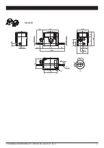
Rear shaft

50

10

Ø 4

27.3

123

(200.3)

125

50

94.8

106

35

71

Ø 12 h 7

Ø 12 h 7

90

45

11.5

11.5

14

14

16.5

(A)

(A)

103.5

79

6.2

10.7

Summary of Contents for FGR1

Page 1: ...oduct and therefore must be kept until the product is dismissed Giovenzana International B V reserves the right to change the features and data shown in this document at any time and without notice Th...

Page 2: ...control system The metal parts of the casing must be connected to the equipotential system in accordance with the instructions in paragraph Connection of earthing or bonding conductors Do not rub the...

Page 3: ...ng 25 70 C storage 30 70 C Options 5 cam shape options 20 pinion options Microswitch technical data Microswitch technical data Operating temperature 25 85 C Minimum life expectancy mechanical electric...

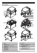
Page 4: ...ase 3 Cover fixing screws 4 Holes for fixing the limit switch M5 5 Front shaft 6 M20 knockout 7 M16 knockout 8 Cable gland M16 9 Sealing ring 10 Cams unit 11 Cams 12 Cam adjustment locking screw 13 Ca...

Page 5: ...1 Rev 4 Dimensions Flanged fixing Base fixing 50 11 5 14 27 3 123 200 3 90 125 94 8 45 106 35 71 12 h 7 16 5 A A 103 5 79 6 2 10 7 10 4 50 10 4 A A 103 5 79 27 3 123 200 3 90 125 140 94 8 106 35 71 6...

Page 6: ...6 GIOVENZANA INTERNATIONAL B V MT FGR1 EN 28 06 2021 Rev 4 Rear shaft 50 10 4 27 3 123 200 3 125 50 94 8 106 35 71 12 h 7 12 h 7 90 45 11 5 11 5 14 14 16 5 A A 103 5 79 6 2 10 7...

Page 7: ...MT FGR1 EN 28 06 2021 Rev 4 INSTALLATION Limit switch installation 79 103 5 120 49 2 M6 4 M6 4 M6 Fixing points for basic configuration Fixing points for flanged configuration Base configuration fixin...

Page 8: ...c 3b 3a 1 Unscrew the 2 screws a and remove the cover b 2 Remove the cable gland a and loosen the sealing nut b to facilitate the insertion of the cable c 3 Insert the cable a into the cable gland b A...

Page 9: ...uitable for a 6 3 0 8 mm contact 1 2 4 NO 1 2 4 NC To wire the microswitches it is necessary to strip the end of the cable 1 5 mm and screw it into the terminal M3 screws 1 2 4 NO 1 2 4 NC To wire the...

Page 10: ...osen the main screw to release the calibration mechanism 4 Adjust each cam a with the calibration screws b The cam must rotate until the microswitch trips c ATTENTION The direction of rotation of the...

Page 11: ...20 16020055 13 16 208 240 170 56 16 18 72 25 13 20 16020056 17 10 170 190 146 6 10 11 7 15 71 20 16020057 13 6 78 90 63 96 6 7 02 9 42 20 16020070 16 19 304 336 266 56 16 18 72 25 13 20 Z Number of t...

Page 12: ...200 113 2 20 23 4 31 42 20 16020059 10 13 130 156 122 56 16 18 72 25 13 20 16020060 12 12 144 168 121 716 12 14 04 18 85 20 16020061 10 14 140 168 107 24 14 16 38 21 99 20 16020062 10 12 120 144 91 9...

Page 13: ...FGR1 EN 28 06 2021 Rev 4 Camshapes GIOVENZANA INTERNATIONAL B V Camshapes Standard A 10 B 60 C 180 16020081 16020097 16020094 10 60 175 21 0 5 80 0 5 186 0 5 D opposite E 10 tips 16020095 16020093 338...

Page 14: ...Maximum axial disalignment obtained without locking screw 1b 1a 2a 4 mm 2b 1b 1a 4 mm 1 Position the two spheres a and the screw b through the central hole and close with an Allen key 2 Make a hole a...

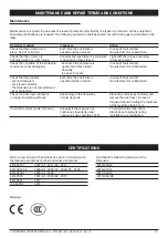
Page 15: ...r for substitution Check that the gaskets are not damaged are placed correctly the thickness is not compromised by compression Each time the enclosure is opened and then closed In case of fault contac...

Page 16: ...16 GIOVENZANA INTERNATIONAL B V MT FGR1 EN 28 06 2021 Rev 4...

Reviews: