MI000003 – rev.00/2016
33
34
35
ALIMENTAZIONE
DI TESTA PRECABLATA
§
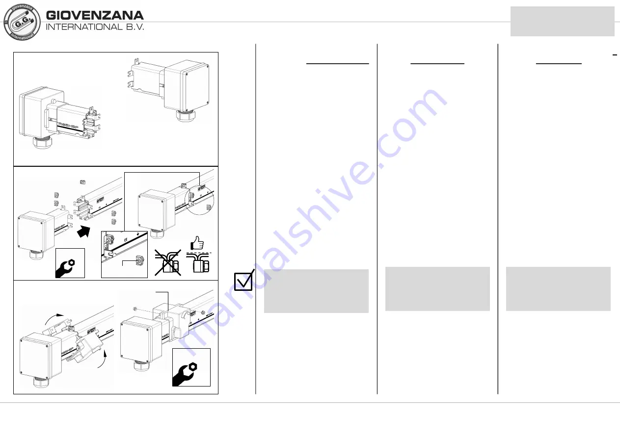
Dis. 33: mostra l’ alimentazione
di testa PRECABLATA in
entrambi i suoi lati.
§
TR85H5P03A4W: 4poli
§
TR85H5P03A5W: 5poli
L’ alimentazione di testa
precablata ha già montato uno
spezzone di barra per cui come
descritto in pag. 12, a seconda di
dove si desidera avere l’
alimentazione a inizio (A) o fine (B)
linea, si deve aver montato le
barre col riferimento di terra dal
lato coincidente.
§
L’ alimentazione PRECABLATA
è già pronta per il montaggio:
§
Dis. 34: rimuovere i morsetti
(cod. ricambio TR8548) e
connettere l’ alimentazione di
testa precablata alla barra.
§
Dis. 35: montare la giunzione
TR8535 come indicato in pag. 19
24
9.6.2
B >
TR85H5P03A4W
TR85H5P03A5W
< A
TR8535W
10mm
Allineare i conduttori per
evitare l’ usura precoce
delle spazzole carrelli e
evitare microinterruzioni
di corrente
10mm
TR8548
КОНЦЕВОЙ ПОДВОД ПИТАНИЯ С
ПРОВОДКОЙ
§
Рис
. 33:
концевой подвод питания с
проводкой
,
показанный с обеих сторон
.
§
TR85H5P03A4W: 4
проводника
§
TR85H5P03A5W: 5
проводников
Концевой подвод питания с проводкой уже
смонтирован с фрагментом секции
шинопровода
,
поэтому как описано на стр
.
12 ,
в зависимости от желания места
положения начала
(
А
)
и конца
(
В
)
линии
,
необходимо монтировать секции следуя
черной линии заземления на боковой
стороне корпуса шинопровода
.
§
Концевой подвод питания с проводкой
уже готов для монтажа
:
§
Рис
. 34:
снять стыковочные зажимы
(
код замены
TR8548)
и подсоединить
подвод питания к шинопроводу
.
§
Рис
. 35:
установить соединительную
муфту
TR8535,
как указано на стр
. 19
Во избежание
преждевременного износа
щеток токосъемника и
прерываний подачи тока
,
выровняйте проводники
HEAD FEED
PRE-WIRED
§
Dwg. 33: shows the head feed
PRE-WIRED from both sides.
§
TR85H5P03A4W : 4 poles
§
TR85H5P03A5W : 5 poles
The pre-wired head feed has a
piece of busbar rail already
mounted and so, as described on
page 12, the busbar rails must
have been mounted with the
earth reference on the matching
side, according to whether it is
wished to have the power feed at
the beginning (A) or the end (B) of
the line.
§
The PRE-WIRED feed is already
prepared for installation:
§
Dwg. 34: remove the terminal
clamps (part no. TR8548) and
connect the pre-wired head feed
to the rail.
§
Dwg. 35: mount the TR8535
joint as indicated on page 19
Align the conductors to
avoid premature wear on
trolley shoes and current
micro-interruptions


