MI000003 – rev.00/2016
51
52
53
INSERIMENTO
GUARNIZIONE
E
CHIUSURA LINEA
§
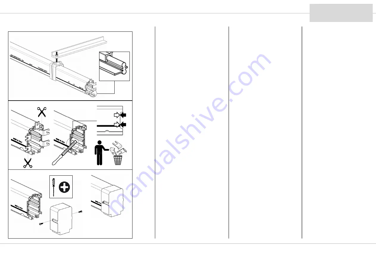
Dis. 51: se previsto inserire la
guarnizione nel labbro inferiore
rivolta come indicato in disegno in
modo che entrambe le parti poi
vadano a chiudere il profilo
limitando così l’ accesso a
polvere.
§
Dis. 52: munirsi di una forbice
industriale oppure una pinza e
rimuovere la parte terminale dei
conduttori. Il taglio deve essere
rifinito e allineato alla barra come
mostrato in disegno.
§
Dis. 53: assemblare il tappo di
chiusura come indicato in disegno
stringendo le due viti laterali.
29
9.9
TR8505W
51
TR8506W
ВСТАВКА
УПЛОТНИТЕЛЬНОЙ ЛЕНТЫ
И
ЗАКРЫТИЕ ЛИНИИ
§
Рис
. 51:
если предусмотрено
,
вставить
уплотнительную ленту в нижнюю выемку
как указано на рисунке
,
таким образом
,
чтобы обе части закрывали шинопровод
снизу
,
тем самым ограничивая доступ
пыли
.
§
Рис
. 52:
с помощью промышленных
ножниц или плоскогубцев отрезать концы
проводников
.
Срез должен быть зачищен
и выровнен с корпусом секции как
показано на рисунке
.
§
Рис
. 53:
установить заглушку как
указано на рисунке и затянуть два
боковых винта
.
SEALING STRIP
INSERTION
AND
LINE TERMINATION
§
Dwg. 51: if applicable, insert the
sealing strip in the lower lip
oriented as shown in the drawing
so that both parts seal the profile
to limit the entry of dust.
§
Dwg. 52: remove the end
portion of the conductors with a
pair of heavy-duty scissors or a
pair of pliers. The cut must be
finished and aligned with the rail
as shown in the drawing.
§
Dwg. 53: mount the end cap as
shown in the drawing and tighten
the two side screws.


