GIRA
Info
Instabus
Continuous Controller
Installation Instructions
Powernet Continuous Controller
19/99
Page: 2 of 3
B
A
C
D
E
F
G
H
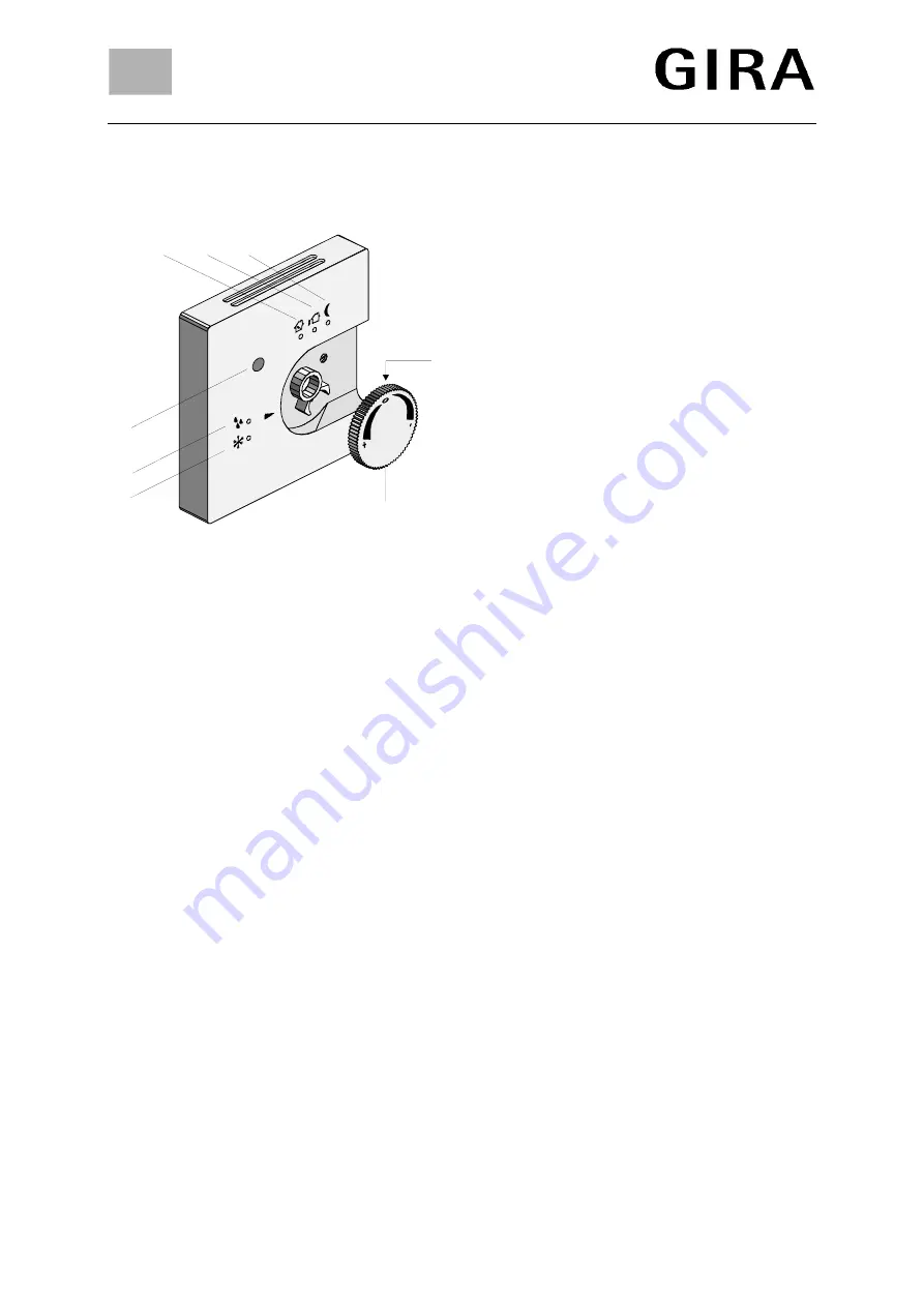
Controls and indicators
(please refer to opposite drawing)
A: Control knob for set value shifting by ± 10 K
max.
(Offset for standby and comfort temperatures
can be parameterised by software.)
B: Setting rings to limit the set value shift
(in the control knob).
C: Presence push-button to continue comfort
mode or to change the mode.
D: Yellow LED to indicate controller locking
(e. g. for dew point alarm).
E: Red LED to indicate frost / heat protection
mode.
F: Green LED to indicate comfort mode.
G: Green LED to indicate standby mode.
H: Green LED to indicate night operation.
Installation
Do not install this device within the range of heat sources. Plug the temperature controller onto a flush-
mounted bus coupler and install it into a standard flush-mounted box.
Contacting is established via the user interface.
For installation, pull off the control knob, plug the temperature controller onto the bus coupler and
secure it with the safety screw (protection against detaching). Return the control knob.
Warning
Caution: The installation and assembly of electrical equipment may only be performed by a
skilled electrician.
Subject to technical modifications.
Please hand this instructions leaflet to your customer after installation.


