background image


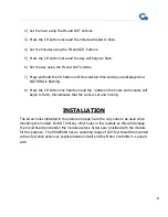
2)


Set the hour using the IN and OUT buttons. 
 

3)


Press the CH button once and the minute will start to flash. 
 

4)


Set the minutes using the IN and OUT buttons. 
 

5)


Press the CH button once and the day will begin to flash. 
 

6)


Set the day using the IN and OUT buttons. 
 

7)


Press and hold the CH button until the selected time and day are displayed but 
NOTHING is flashing. 
 

8)


Press the CH button one final time and the : between the hours and minutes will 
begin to flash, this indicates that the clock is set and running. 


INSTALLATION 

The screw holes indicated in the picture on page 5 are the only ones to be used when 
mounting the module. Do NOT drill any other holes in this module as this will damage 
the circuit board and render the module useless. Screws are provided with the module 
for this purpose.  The 98GC661B has an operating range of 100’ but should be mounted 
with as few obstructions as possible between itself and the Motor Controller it is paired 
with. 


Summary of Contents for 98GC661B

Page 1: ...98GC661B 5 CHANNEL WALL SWITCH INSTALLATION AND PAIRING GUIDE RV AWNING PRODUCTS 1361 CALLE AVANZADO SAN CLEMENTE CA 92673 949 259 4000 FAX 949 276 5500 www girardrv com ...

Page 2: ...ing your awning ensure that the area into which the awning will be deployed is free of obstructions Trees walls pillars posts other vehicles etc Damage caused by collisions with any of the above or similar is not covered by warranty Before using your awning make sure that all of your electrical circuits are operating correctly Recreational Vehicles can generate AC power from three separate sources...

Page 3: ...motors and control modules provided by Girard Systems communicate by use of RF signals on a frequency of 433 92 MHZ This eliminates the need for wiring and the drilling of holes in the vehicle These components must be electronically matched or paired before use This is usually done at the Girard Systems factory Should the need arise for the user to pair a device with the motor controller they must...

Page 4: ... control a single awning by means of a 6 button control pad as seen in the picture below The faceplate can be removed easily by holding the module at the left and right edges firmly in one hand and push the STOP and P2 buttons with two fingers of your other hand The picture below shows how the batteries must be inserted ...

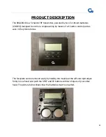
Page 5: ...tions as a 24 hour clock and a 7 day calendar When the battery tray is inserted the display will light up as in the photograph above then it will default to Mon 10 00 Replace the faceplate then 1 Press and hold the CH button until the hour starts to flash Screw mounting holes ...

Page 6: ...H button one final time and the between the hours and minutes will begin to flash this indicates that the clock is set and running INSTALLATION The screw holes indicated in the picture on page 5 are the only ones to be used when mounting the module Do NOT drill any other holes in this module as this will damage the circuit board and render the module useless Screws are provided with the module for...

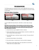
Page 7: ...l revert to factory settings It is highly recommended that you read and understand the following sequence before attempting to execute it 1 Ensure that there is power supplied to the Motor controller 2 Using an appropriate tool press the Program button on the Motor controller See Fig 1 The Green LED will start blinking 3 Press the STOP button on the Motor Controller See Fig 2 The Green LED will re...

Page 8: ...d that you read and understand the following sequence before attempting to execute it 1 Ensure that there is power supplied to the Motor controller 2 Press the Program button on the Motor controller The Green LED will start blinking 3 Press the STOP button on the Motor Controller The Green LED will remain ON 4 Select the desired channel on the wall switch 5 Press the IN button on the Wall switch T...

Page 9: ...er to the motor control module It will beep ONCE 2 Press the P2 button on the wall switch TWICE The motor controller will beep with each press 3 Select the desired channel on the wall switch 4 Press the IN button on the wall switch The awning should retract If the awning extends at this point instead of retracting press the STOP button immediately then remove the power supply to the motor controll...

Page 10: ...stand the following sequence before attempting to execute it 1 Ensure that there is power supplied to the Motor controller 2 Press the Program button on the Motor controller The Red LED will start blinking 3 Press the STOP button on the Motor Controller The Red LED will remain ON 4 Select the desired channel on the wall switch 5 Press the IN button on the Wall switch The Red LED will extinguish Pr...

Page 11: ...ch operates the DC Motor controller for the awning that the wall switch is to operate This is likely to be either a 98GC1063 Single channel or a 98GC1029 Multi channel handset Fully extend the awning to ensure smooth operation and then retract the awning leaving it partially open about 3 feet Locate the P2 Button on the back of the handset P2 Button ...

Page 12: ...tton on the wall switch ONCE The GC1146C will beep again 5 Press the IN button on the wall switch and verify that the awning moves in the desired direction If the awning extends at this point instead of retracting press the STOP button immediately then remove the power supply to the motor controller for at least 10 seconds Next repeat steps 1 2 and 3 above then press the OUT button on the wall swi...

Reviews: