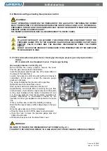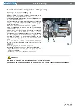
Steps for the connection
61
Code no. 550038
Rev. no. 16/1018
5.2.1. Installation characteristics
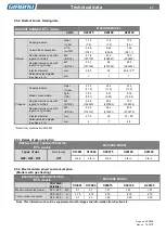
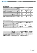
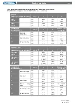
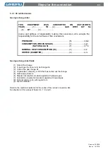
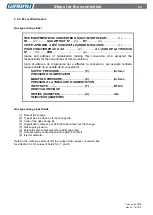
See the
Technical and Connection Details
for the
corresponding model (Chapter 4) for values regarding
connection pressure, power consumption, and the diameter
and position of the connection.
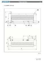
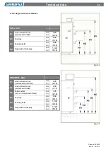
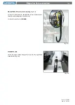
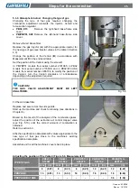
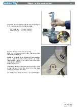
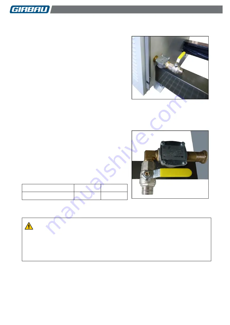
PB32, X13. Gas connection
Fig. 5.7
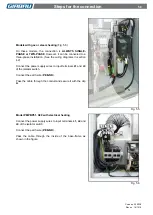
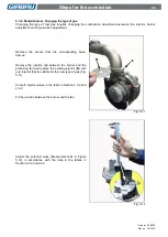
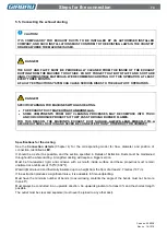
PB/PBP51, X20. Gas connection
Fig. 5.8
Installation requirements
In order to ensure the supply pressure indicated, both at the
input of the regulator and the input of the machine, it is
recommended to:
Install a pressure regulator capable of supplying the
required flow, and fit a pressure gauge to the regulator
inlet and outlet.
Ensuring that the gas conducting pipe is of a sufficient
size.
Avoiding, if possible, the use of flexible joints.
As protection for the burner, it is recommended to
install a device to protect against excess pressure.
5.2.2. Connecting the machine to the supply network
The connection should be made at the input to the burner,
located at the rear of the machine (Fig. 5.7 and 5.8).
The machine intake connection pipe is:
CE
certified models.
BSP
thread
3/4 in
ETL
certified models.
NPT
thread
3/4 in
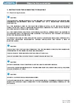
DANGER!!
IN ANY OPERATING CONDITION, THE PRESSURE OF THE GAS SUPPLY ENTERING THE IRONER
MUST CORRESPOND TO THE PRESSURE INDICATED IN SECTIONS 4.3, 4.4 AND 4.5 OF THIS
MANUAL. PRESSURES OTHER THAN THOSE INDICATED MAY CAUSE THE IRONER TO
MALFUNCTION AND PRESENT A RISK OF SERIOUS INJURY.
THE MANUFACTURER DECLINES ALL RESPONSIBILITY IN THESE CASES.

