8-
9
m
m
1
NA
1
sp
ee
d
4
2
3
1
4
4
1
sp
ee
d
3
3
3
4
2
sp
ee
d
2
sp
ee
d
2
re
d
2
1
re
d
1
2
1 10 4 3
4
3
1
2
1
0
1
2
3
4
10
L3
L2
L1
PE
13
Swiss Lifting Solutions
Figure 2-4
Figure 2-5
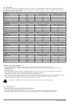
The protective conductor should not conduct any current during operation. With the installation of a motor protection breaker,
the current of the electric chain hoist must be observed in accordance with the type plate.
• Checking direction of rotation: If the directions of movement do not match the button symbols of the control switch, the
supply line wires L1 and L2 must be transposed.
• In the single-phase version, inching operations can cause malfunctions.
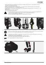
• With the cover removed, observe the rotating fan wheel (1, see Figure 2-4).
Open the terminal used in accordance with figure 2-5.
Figure 2-1
Figure 2-2
Figure 2-3
• Before connecting the electric chain hoist, check whether the operating voltage and frequency specified on the type plate
correspond to the available power supply.
• Remove the cover from the control unit box.
• Introduce the connection cable with cable gland M25 × 1.5 through the lower or side hole and connect in accordance with
the attached electrical chart to L1, L2, L3 and PE (see figure 2-1).
• Introduce the control cable through cable gland M20 × 1.5 in the hole below the housing and connect to terminals 1, 2, 3, 4, 10
(see figure 2-2).
• Mount strain relief to housing (see Figure 2-3).
• Re-fit the cover from the control unit box.
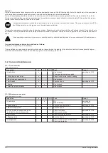
• To maintain the predetermined protection class IP 65, all cables must fit into the corresponding cable glands and the
cover screws must be tightened after the connection with the torque specified in table 3.2.8.
• Open holes must be provided with a sealing plug.
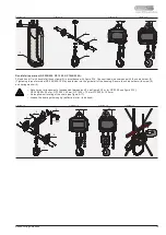
• The control switch must be attached to the strain relief cord and not to the cable.


