

Handling instructions
for GISMA connectors
HI
– 2007 - 001
Document: replaces
MV 2000-020,
MV 2000-030 and
MV 2005 - 011
First issue:
15.07.2008
Rev.-Index: -Z-
From:
29.07.2020
Copyright by:
GISMA GmbH
Page 11 of 44
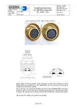
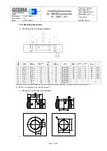
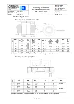
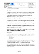
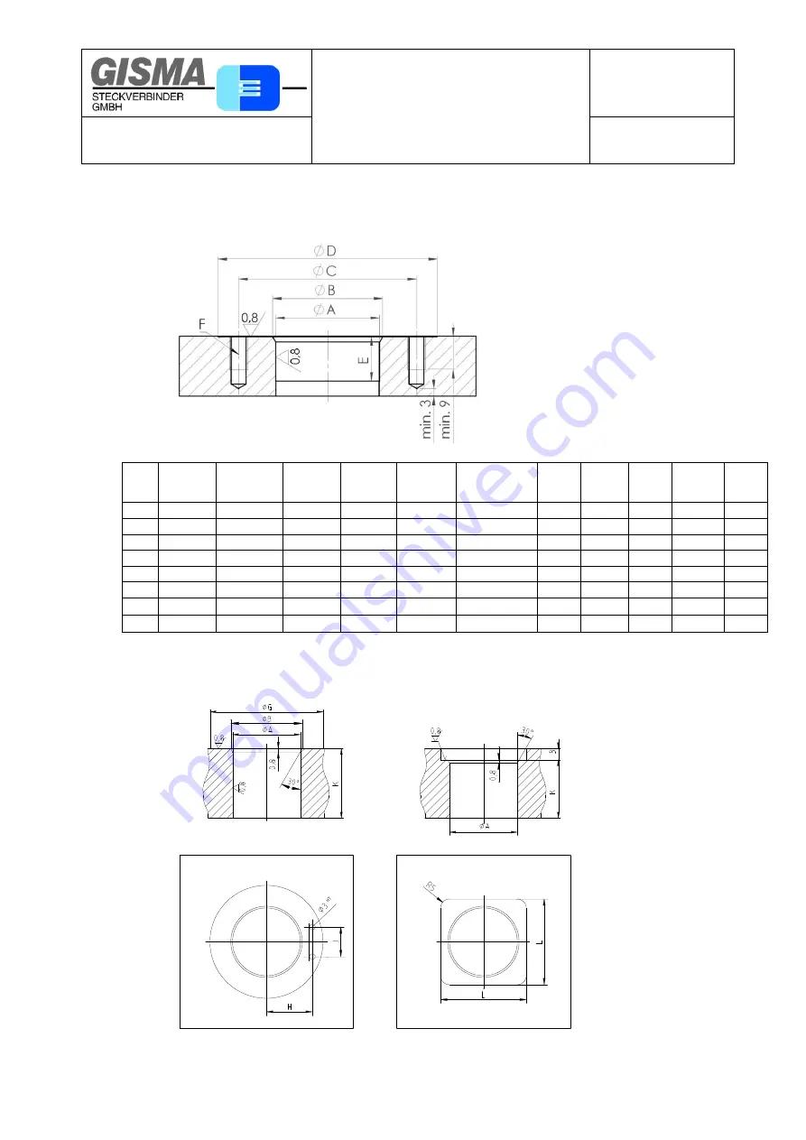
7.1.6. Mounting dimensions
Mounting hole for flange-receptacle
Siz
e
Ø A
Ø B
max.
Ø C
±0,1
Ø
D
min.
Ø E
min.
Ø F
Ø G
H
±0,1
J
±0,2
K
max.
L
1
23,5
H8
24,5
-0,3
37,5
50
12
M5 (4x90°)
36
17,7
11
28
32,6
2
26,5
H8
27,5
-0,3
40
51
12
M5 (6x60°)
39
19,2
11
28
35,6
3
32
H8
33,5
-0,3
48
59
12
M5 (6x60°)
46
22,2
15
26
41,6
4
36,5
H8
37,5
-0,3
52
63
12
M5 (6x60°)
51
24,7
16
26
46,6
5
47
H8
49,5
-0,3
67
78
12
M5 (6x60°)
69
32,7
24
25
62,6
6
56
H8
59,5
-0,3
77
88
17
M5 (6x60°)
78
39,2
14
25
75,6
7
85
H8
88
-0,3
112
126
28
M8 (6x60°)
71
91
H8
94
-0,3
122
142
17
M8 (6x60°)
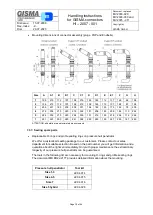
Mounting holes for standard flange and jam nut receptacles. Please, contact our design department for special ones!
ATTENTION: for application more than 600 bars Ø C
H7.
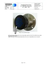
Mounting hole for jam nut receptacle


