21
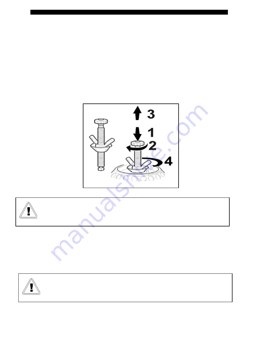
There is a driving pin on the spindle flange that is to be fitted in one of the rim clamping holes.
Position the ring nut hub and the appropriate nose on the spindle flange in relation to the diameter of the drop centre
hole.
Proceed as follows to couple the hub correctly:
- Turn the hub clockwise by hand until you find the exact coupling position.
- Press the hub and turn clockwise by 90° as far as it will go.
- Release the pin and make sure it raises by approximately 10mm, otherwise turn it slightly clockwise and/or anti-
clockwise forcing the pin upwards so that it lifts.
- Position the nose in contact with the rim, perfectly centred with the drop centre hole. The nose has a split that must
match-up (if necessary) with the driving pin.
- Tighten the ring nut so that it moves up to the nose and continue to tighten so that the wheel is pushed firmly on the
flange of the spindle.
ATTENTION:
Before you start any work on the wheel, make sure it is clam-
ped perfectly on the spindle
14.1_BEAD BREAKING
DEFLATE
the tyre completely by removing the valve before starting any work.
- Using an appropriate tool, remove all the counterweights from the rim, being very careful not to damage it.
ATTENTION:
Do NOT start any work on the wheel before the tyre is comple
-
tely deflated.
- Before starting any work, make sure there is no pressure sensor, otherwise check its state of efficiency using a spe-
cial tester
Summary of Contents for Crossage
Page 1: ...Original Instructions Ed 01 11 Cod 3019988 Use and Maintenance instruction manual...
Page 41: ...41 WIRING DIAGRAMS...
Page 42: ...42...
Page 43: ...43...
Page 44: ...44 PNEUMATIC DIAGRAMS...
Page 45: ...45 Optional...
Page 46: ...46...
Page 47: ...47 SERVICE REGISTER...


