30
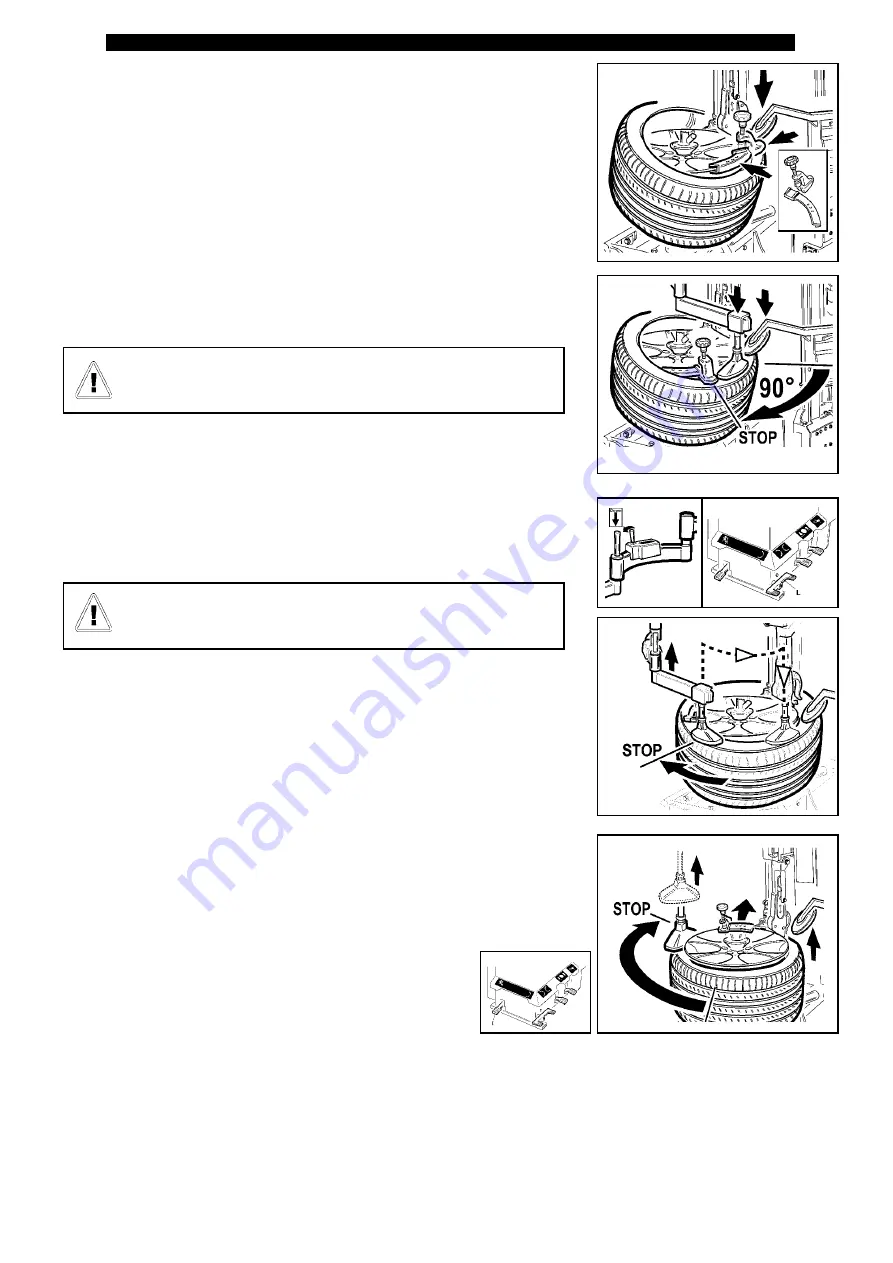
Make sure the bead of the tyre rests on the “shoe” shaped part of
the tool and under the grub screw in the opposite part of the tool.
-Position the tyre horizontally on the rim, slightly tilted downwards in the “3
o’clock” position (fig. 27).
- Insert and secure the clamp with the rubber protector suitable for the type of
rim ( • iron rim •• alloy rim ••• alloy rim with protruding spokes).
- If necessary, exploit the top disc positioned near the clamp (fig. 27).
- The clamp and its protector must be positioned before the valve (Fig.27)
- Position the bead breaking disc at the height of the channel, turn slightly
and insert the bead presser between the disc and the clamp and press until it
reaches the channel (fig.28)
- Start turning, when the clamp is roughly in the “6 o’clock” position, make
sure the whole bead within this section is right inside the channel..
- If this is not the case, which is an indispensable condition to be able to
mount the tyre correctly, use the mobile bead presser to push the bead in the
channel, pressing roughly in the “3 o’clock” position, and where necessary, to
insert the bead of the tyre in the channel of the rim (fig.29)
- Start turning again until the upper bead is fitted completely in place (fig. 30).
- Remove the clamp and the protector, pushing the bead breaking disc. Re-
move the mobile bead presser and raise the bead breaking disc. (fig.30)
- Tilt the vertical arm backwards by pressing pedal
I
out of the work area.
ATTENTION:
In these last phases, work very carefully to avoid strai
-
ning the side of the tyre excessively.
Fig. 30
Fig. 27
Fig. 28
Fig. 29
Summary of Contents for Crossage
Page 1: ...Original Instructions Ed 01 11 Cod 3019988 Use and Maintenance instruction manual...
Page 41: ...41 WIRING DIAGRAMS...
Page 42: ...42...
Page 43: ...43...
Page 44: ...44 PNEUMATIC DIAGRAMS...
Page 45: ...45 Optional...
Page 46: ...46...
Page 47: ...47 SERVICE REGISTER...


