9
9.2 Tyre-Changer placement and connections
Place Tyre-Changer
onto a levelled-out, smooth and not slippery floor with a suitable load capacity.
No bolt down installation is required. In case of bolt-down installation, please refer to all 4 holes on the base of the ma
-
chine, drilling through 100 mm into the floor and using suitable bolts for fixing.
If the machine is installed outside it must be protected by a appropriate lean-to shed.
The electric network of the installation area must be provided with adequate earth plate and connected to an automatic
circuit-breaker (differential) set at 16 mA.
Should the Tyre-Changer
be lacking in electric plug, the user must set one - at least 16 A and conform to the voltage of
the machine, in compliance with the regulations in force.
Before connecting the machine, please check that the characteristics of your networks
correspond to those indicated by machine’s data-label.
Even small jobs done on the electrical system must be carried out by professionally qualified
personnel.
The Manufacturer is not responsible for damages caused by electrical connection different
from the original indications.
The pneumatic network of the installation area must be provided with
min. 8 bar working pressure outlet.
Connect the machine to the pneumatic network by means of the air fitting on oiler filter/
regulator installed onto the rear section of the machine.
Unplug the unit from electrical and pneumatic outlets before moving and servicing.
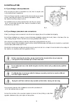
fig. 4
9.0 INSTALLATION
9.1 Tyre-Changer site requirements
When choosing the place of installation be sure that it complies with
current safety-at-work regulations.
The Tyre-Changer must be connected to the main electric power supply
and the compressed air system. It is therefore advisable to install
the machine near these power sources.
The installation area must leave at least the room shown in picture
“fig. 4”, so as to allow all parts of the machine to operate correctly
and without any restriction.


