background image

69

SCHEMA ELETTRICO PEDALIERA - 

PEDAL CONTROL UNIT - ELECTRICAL DIAGRAM-SCHEMA ELECTRIQUE PEDALIER-PEDALSTEUERUNG - SCHALTPLAN

Summary of Contents for S 551 XL A

Page 1: ...RSAL S 551XL A MANUALE DI ISTRUZIONI PER L USO E LA MANUTENZIONE USE AND MAINTENANCE INSTRUCTIONS MANUAL D INSTALLATION D UTILISATION ET D ENTRETIEN INSTALLATION BEDIENUNG UND WAR TUNG MANUAL DE INSTR...

Page 2: ...RMITE CE CE BEREINSTIMMUNG DECLARACION CE DE CONFORMIDAD al quale questa dichiarazione si riferisce E CONFORME ALLE SEGUENTI DIRETTIVE to which declaration refers is in conformity with the FOLLOWING D...

Page 3: ...en Vorschrift durchgef hrt werden e le disposizioni di Legge del Paese di destinazione della macchina apparecchiatura as well as with the national laws in force in the Country of Installation ainsi qu...

Page 4: ...ter le constructeur ou les revendeurs autoris s This equipment is subject to the regulations foreseen by Directives 2002 96 CE and 2003 108 CE RAEE and therefore it cannot be scrapped as a generic scr...

Page 5: ...ONTROLE DU BON FONCTIONN 13 UTILISATION 13 1 Blocage de la roue Blocage des jantes en alliage 13 2 Roues tubeless et supersingle D talonnage D montage Montage 13 3 Roues chambre air D talonnage D mont...

Page 6: ...g instructions It is forbidden to use the machine for straightening rims breaking beads of still inflated or dirty tyres turning rasping cutting tyres The Manufacturer shall not liable for any injury...

Page 7: ...Maschine darf nur von Personal benutzt werden das speziell angeleitet wurde und dazu eine Genehmigung hat Jede Umr stung oder nderung der Maschine die vorher nicht vom Hersteller genehmigt worden ist...

Page 8: ...Fig B 2 Limita la massima pressione sul circuito oleodinamico salvaguardan do il buon funzionamento dell impianto 3 Interruttore magnetotermico di protezione del motore pompa situato all interno della...

Page 9: ...aschine in drei ver schiedenen Packversionen ausgeliefert 1 in Holzkiste auf Palette 2 auf Palette verankert 3 ohne Verpackung In der ersten und der zweiten Version mu die Maschine mit einem Gabelstap...

Page 10: ...ture from 0 55 C UNPACKING B 5 A 7 1 7 1 INSTALLATION PLACE LUOGO DI INSTALLAZIONE 2500 mm 2500 mm 1000 mm 700 mm ATTENZIONE Non consentito l utilizzo della macchina in atmosfera esplosiva ATTENTION T...

Page 11: ...los siguientes requisitos Humedad relativa del 30 al 95 sin condensaci n Temperatura de 0 a 55 ACHTUNG Es ist nicht gestattet die Maschine in explosions gef hrdeten R umen zu benutzen ATTENTION Il es...

Page 12: ...must be installed on a levelled concrete floor at least 20 cm thick with a minimum concrete quality of B25 in accordance with DIN 1045 requirements foundations Foryourreferenceseethesidedrawingaswell...

Page 13: ...nden Die Verankerungsschraube in jede Bohrung einsetzen Die Verankerungsschrauben m ssen mindestens 125 mm in den Beton hineinragen siehe Abbildung Die Verankerungsschrauben festspannen Bei Verwendung...

Page 14: ...della centralina oleodinamica sia quello indicato dalla freccia 6 fig B 6 In caso contrario fare invertire tra loro da personale specia lizzato due fili nella spina CONTROLLO SENSO DI ROTAZIONE Before...

Page 15: ...Maschine die Stromaufnahme ab und pr fen Sie ob das fragliche Stromnetz damit belastet werden kann Jeder Schaden der sich aus der Nichtbeachtung dieserAnweisungen ergibt enthebt den Hersteller von jed...

Page 16: ...ti possono costituire pericolo per chi opera Per lo stesso motivo eventuali capelli lunghi dovranno essere raccolti 1 Staffa di sollevamento 2 Braccio porta autocentrante 3 Autocentrante 4 Pedana 8 Ma...

Page 17: ...8 Steuergriff 9 Schalter 10 Kippedal 13 Schlitten 14 Werkzeugtragearm 15 Armhebel 17 Abdr ckscheibe 18 Hakenwerkzeug 22 Spannklaue ATTENTION Pendant le travail tenir les mains et les autres parties d...

Page 18: ...e Non utilizzare lo smontagomme se mancante di una o pi targhette di pericolo Non interporre oggetti che ne ostrui scano la visione all operatore Per eventuali richieste utilizzare il codice indicato...

Page 19: ...add any object that could prevent the operator from seeing the labels Use the code in this table to order labels you need ATTENTION Si les plaques signal ti ques de danger sont peu lisibles ou si elle...

Page 20: ...s A B C D referred to in the following pages describing how to use the tyre changer Use of these positions ensures greater precision speed and safety for those using the machine The mobile control cen...

Page 21: ...fig C en position e d gage et renverse l ou til en position f l accroche et le d place en position de travail en position g il d place le chariot outil vers gauche et en position h il le d place vers...

Page 22: ...ould open move the lever down and the spindle arms should close 3 Push the lever 11 fig C upwards e to have the tool arm 14 fig D released and tilted outwards push the lever downwards f to have the to...

Page 23: ...f pour bloquer le bras porte outil en position de travail Actionner le manipulateur droite h pour d placer le chariot porte outil droite l actionner gauche pour d placer le chariot au c t oppos 1 Acti...

Page 24: ...are la ruota all autocentrante traslando la pedana mobile quindi agire sull inter ruttore 9 fig C per aprire l autocentrante e bloccare cos il cerchio internamente e nella posizione pi conveniente DAN...

Page 25: ...ieur dans la position la plus appropri e UTILISATION 13 2 Colocar en posici n de reposo el brazo porta tiles 14 Fig D 3 Accionando el manipulador alejar la peana m vil 13 Fig D del autocentrante y lev...

Page 26: ...gr with central hole the wheel can be locked with the 4 extensions 140 90 BLOCCAGGIO CERCHI IN LEGA ATTENZIONE Non abbandonare il posto di lavoro con la ruota bloccata sull autocentrante e sollevata d...

Page 27: ...ES EN ALLIAGE ATTENTION N abandonnez pas le poste de travail avec la roue bloqu e sur le mandrin et soulev e du sol au type de jante voir les figures E 1 E 2 E 3 E 4 E 5 E 6 Sachez que le blocage sur...

Page 28: ...di lavoro potrebbero schiacciarsi tra l utensile stesso e la ruota 8 Premere la leva 15 fig G e ruotare di 180 l utensile che si bloccher automaticamente Ripetere le operazioni precedentemente descrit...

Page 29: ...y contempor neamente avanzar con el disco destalonador con breves impulsos siguiendo lo mejor po sible el perfil de la llanta 6 Avanzar hasta separar por completo el primer tal n Para agilizar la ope...

Page 30: ...ubeless pu avvenire in due modi 1 Se la ruota non presenta difficolt di smontaggio pro seguire dopo la stallonatura spingendo con il disco stallontore sul fianco interno del pneumatico fino a far usci...

Page 31: ...erkzeug rutscht Den beweglichen St nder in die Arbeitsposition C bringen Den beweglichen St nder in die Arbeitsposition B bringen DESMONTAJE Introducir la palanca 17 Fig I entre llanta y tal n a la de...

Page 32: ...er the bead breaker disk or the hook tool If the tyre is not problematic use the bead loosener disk If the tyre is very rigid the hook tool must be used MONTAGGIO CON DISCO Agire nel modo seguente 1 S...

Page 33: ...ben wird 2 Die Reifenw lste und die Felge mit der Seifenlauge schmieren 3 Die Zange am Au enhorn der Felge befestigen und zwar an der h chsten Stelle vgl Abb M 4 Den Reifen auf die Plattform stellen u...

Page 34: ...utocentrante avendo cura di sostenere la ruota per evitarne la caduta 13 Close the arms of the spindle completely Support the wheel to prevent it falling off 14 Traslare la pedana in modo da liberare...

Page 35: ...e an der Zange befestigen vgl Punkt 4 Die Felge mit dem angehakten Reifen heben und 15 20 cm im Ge genuhrzeigersinn verdrehen Zange in 10 Uhr Stellung beiden einhaken Dann vorgehen wie unter Punkt 10...

Page 36: ...n posizione di fuori lavoro traslarlo sul fianco esterno del pneumatico e riagganciarlo in questa posizione 9 Ruotare l utensile di 180 agendo sulla leva 15 Fig D 10 Montare la pinza nel punto pi in b...

Page 37: ...Werkzeug mit Hebel 15 Abb D um 180 verdrehen 10 Die Zange an der tiefsten Stelle 6 Uhr Stellung au erhalb des zweiten Wulstes montieren vgl Abb N 11 Das Spannfutter im Uhrzeigersinn um circa 90 drehen...

Page 38: ...mobile in posizione di lavoro C 1 Tip the tool carrier arm 14 Fig D to its non working position Move it to the outside plane of the wheel and rehook it in this position 2 Rotate the wheel and at the...

Page 39: ...wird da der Wulst vom Werkzeug rutscht 4 Das Hakenwerkzeug nach au en fahren bis der rote Bezugspunkt sich in der N he der Felgenau enkante befindet DEMONTAGE Den beweglichen St nder in die Arbeitspo...

Page 40: ...reference dot is about 3 cm inside the rim 13 Insert lever between rim and bead at the right of the tool See Fig Q 14 Press down on the lever and lower the wheel to bring the edge of the rim about 5 c...

Page 41: ...en Hebel gedr ckt halten und das Rad senken bis das Felgen horn einen Abstand von circa 5 mm vom Hakenwerkzeug hat Dann das Rad im Gegenuhrzeigersinn verdrehen bis der Wulst ganz von der Felge gel st...

Page 42: ...autensili in posizione di fuori lavoro traslarlo sul fianco esterno del pneumatico 12 Ruotare l utensile di 180 agendo sulla leva 15 Fig D Portarsi con la colonnetta mobile in posizione di lavoro D Ta...

Page 43: ...ellung au er Betrieb bringen ihn auf die Au enseite des Reifens verfahren und in dieser Stellung wieder einrasten lassen 12 Das Werkzeug mit Hebel 15 Abb D um 180 verdrehen 13 Das Spannfutter verdrehe...

Page 44: ...o its working position 22 Bring the tool forward until the red reference dot is lined up with the outside edge of the rim and about 5 mm from it 23 Turn the spindle a little clockwise until you can in...

Page 45: ...it der Nutmutter befestigen und die Verl ngerung abnehmen 29 Die Spannklauen auf dem Spannfutter ganz schlie en und das Rad unterst tzen damit es nicht f llt 16 Girar el autocentrante hasta colocar la...

Page 46: ...ticale del pneumatico 13 Abbassare l autocentrante fino a che il pneumatico non appoggi sulla pedana RUOTE CON CERCHIETTO WHEELS WITH SPLIT RING STALLONATURA E SMONTAGGIO BEAD BREAKING AND DEMOUNTING...

Page 47: ...tfernen Den Sperrkegel ausrasten und denArm in die Position au er Betrieb heben Den Werkzeugtragearm auf die Radinnenseite bringen 9 Den Hebel 15 Abb D dr cken und das Werkzeug um 180 ver drehen bis e...

Page 48: ...el so that the bead breaker disk touches up against outside edge of the centre well rim 4 Turn the spindle and at the same time move the bead breaker disk forward until the split ring is detached Watc...

Page 49: ...ich ganz von der Felge gel st hat Dabei auf das Ventil achten R DER MIT 5 TEILIGEM SPALTRING 1 Das Rad wie vorstehend beschrieben auf dem Spannfutter aufspannen Sicherstellen da die Luft aus dem Rad a...

Page 50: ...hietto al cerchio e di stallonarli contemporaneamente DANGER The tyre is not attached to the split ring completely safely Any strain on it during positioning or clamping operations could cause it to d...

Page 51: ...sch lieferbar benutzt die es erm glichen den Spaltring an der Felge zu befestigen und beide gleichzeitig abzudr cken ACHTUNG Wenn der Reifen sich von der Felge trennt f llt er auf den Boden Daher imme...

Page 52: ...work position with the disk towards the wheel NB If the tyre is not inserted sufficiently on the rim move the spindle until the tyre bead is by the disk Bring the disk forward with the spindle turnin...

Page 53: ...reit wird 10 Das Rad herunternehmen R DER MIT 5 TEILIGEM SPALTRING 1 Den Spannfutterarm in die Position au er Betrieb bringen Wenn die Felge vom Spannfutter heruntergenommen worden ist mu sie wieder a...

Page 54: ...s work position with the bead breaker disk turned towards the wheel NB If the split ring is not inserted sufficiently on the rim move the spindle until the split ring is by the disk Bring the disk for...

Page 55: ...en wobei man sich wie in Abb Y gezeigt mit dem Abdr ckscheibe hilft Den Werkzeugtragearm in die Position au er Betrieb bringen und die Spannklauen des Spannfutters ganz schlie en wobei zu beachten ist...

Page 56: ...che con il braccio porta autocentrante abbassato a fine corsa non deve mai scoprire completamente la spia situata sul carter riduttore Se necessario rabboccare con olio ESSO SPARTAN EP 320 o equi val...

Page 57: ...en Sie ein allgemein bliches Schmierfett 3 Pr fen Sie regelm ig den lstand in der hydraulischen Krafteinheit Dazu ist ein lme stab unter dem Stopfen derselben vorhanden Falls erforderlich l der folgen...

Page 58: ...iona CAUSE 1 L interruttore magnetotermico di protezione del motore entrato in funzione CAUSES 1 The magneto thermic switch for motor protection is working RIMEDI 1 Chiamare l assistenza tecnica per v...

Page 59: ...ufen zu bringen oder wenn St rungen irgendwelcher Art vorliegen verwenden Sie die Maschine NICHT sondern verst ndigen umgehend den technischen Kundendienst ST RUNGEN 1 Den Stecker richtig in die Netzs...

Page 60: ...neggiare in caso di essicazione l autocentrante la guida del braccio porta utensile le guide del carrello l utensile Svuotare eventuali serbatoi contenenti liquidi di funzionamento e prov vedere alla...

Page 61: ...den k nnten wenn sie aus trocknen das Spannfutter die F hrung des Werkzeugtragearms die Schlittenf hrungen das Werkzeug Die Beh lter entleeren die f r den Betrieb erforderliche Fl ssigkeiten enthalten...

Page 62: ...ing a diameter of 46 and without a flange with a central hole 141 90 Bead guide lever It facilitate bead mounting of tubed wheels 20 ACCESSORI 20 ACCESSORIES 19 Sul retro dell apparecchiatura posta un...

Page 63: ...digen 140 90 Arretierverl ngerungen Bei Felgen mit einem Durchmesser von mehr als 46 ohne Flansch mit zentralem Loch 141 90 Wulstf hrungshebel Vereinfacht die Montage der W lste bei Schlauchreifen 20...

Page 64: ...64 SCHEMA ELETTRICO ELECTRIC DIAGRAM SCHEMA ELECTRIQUE SCHALTPLAN ESQUEMA ELECTRICO 1 110 V 1 ph...

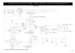
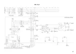
Page 65: ...65 230 V 1 ph...

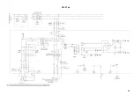
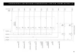
Page 66: ...66 220 V 3 ph...

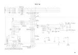
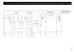
Page 67: ...67 400 V 3 ph...

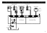
Page 68: ...68 SCHEMA ELETTRICO ELECTRIC DIAGRAM SCHEMA ELECTRIQUE SCHALTPLAN ESQUEMA ELECTRICO 2...

Page 69: ...69 SCHEMA elettrico pedaliera PEDAL CONTROL UNIT ELECTRICAL DIAGRAM SCHEMA ELECTRIQUE PEDALIER PEDALSTEUERUNG SCHALTPLAN...

Page 70: ...ilindro ribaltamento utensile B1 A1 B2 A2 B3 A3 B4 A4 B5 A5 BLOCCO IDRAULICO S551 COD 2012881 BLOCCHETTO 2 FUNZIONI AGGIUNTIVO COD 4194250 TL PL Cilindro traslazione dx sx utensile A B Y14 Y13 Y26 Y27...

Page 71: ...chiudi autocent Turntable opening closing control switch S7 Rotazione autocent oraria Turntable clockwise rotation S8 Rotazione autocent antioraria Turntable anticlockwise rotation T1 Trasformatore mu...

Page 72: ......

Reviews:

Related manuals for S 551 XL A