background image

62

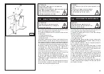
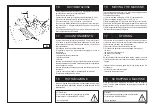
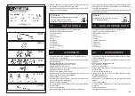
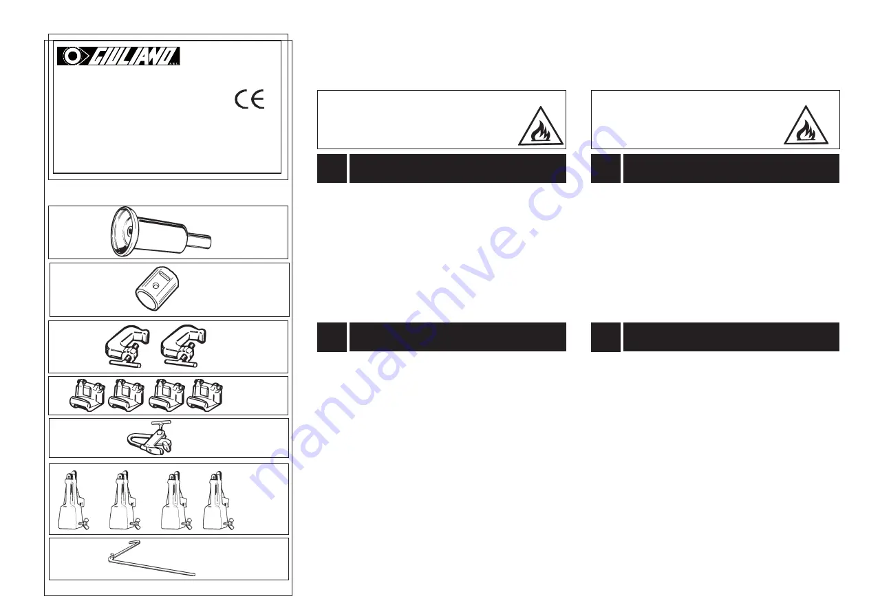
Gli accessori disponibili, a richiesta, per lo smontagomme sono:

135/90 Rullo per ruote tubeless

Montato sul braccio porta utensili agevola le operazioni di stallonatura 

delle ruote tubeless.

268/04 Kit adattatore per rullo ruote tubeless

Da utilizzare in abbinamento con ART. 135/90

136/90 Coppia di morsetti con vite

Utilizzati sulle ruote con cerchietto consentono la stallonatura con-

temporanea di cerchio e cerchietto.

137/90 Serie di griffe per cerchi in lega

Montate sulle griffe dell'autocentrante consentono di operare sui 

cerchi in lega senza rischiare di danneggiarli.

138/90 Pinza per cerchi in lega 

Da utilizzare in alternativa alla pinza  . Consente di operare sui cerchi 

in lega senza rischiare di danneggiarli.

140/90 Prolunghe di bloccaggio

Per cerchi diametro interno superiore a 46" e non provvisti di flangia 

con foro centrale

141/90 Leva guida talloni

Agevola il montaggio dei talloni delle ruote con camera d'aria.

The following optional accessories are available for the tyre changer:

135/90 Tubeless roller

Mounted on th tool holding arm, it facilitates bead breaking of tube-

less wheels.

268/04 Adaptor for tubeless tyres roller

To be joined to Art. 135/90

136/90 Pair of bead clamp

Used on wheels with split ring, they allows bead breaking of both 

rim and split ring.

137/90 Set of 4 jaws for alloy rims

Mounted on the jaws of the chuck, they allows to operate on alloy 

rims without damaging them.

138/90 Pliers for alloy rims 

Used instead of  , they allows to work with alloy rims without damag-

ing them.

140/90 Locking extension

For rims exceeding a diameter of 46" and without a flange with a 

central hole.

141/90 Bead guide lever

It facilitate bead mounting of tubed wheels.

20

ACCESSORI

20

ACCESSORIES

19

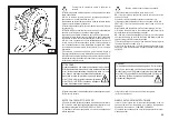
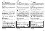
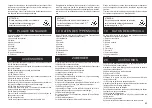
Sul retro dell'apparecchiatura è posta una targhetta di 

identificazione della macchina riportante:

1-Dati del costruttore

2- Modello

3- Numero di serie

4- Fase

5- Voltaggio

6- Frequenza

7- Assorbimento

10- Anno di costruzione

11- Peso

The manufacturer’s Serial plate is fixed on the back of the 

machine. If gives the following information:

1- Manufacturer information

2- Model

3- Serial number

4- Phases

5- Voltage requirements

6- Frequency

7- Rated draw

10- Year

10- Net weight

DATI DI TARGA

19

DATA ON SERIAL PLATE
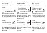
ATTENZIONE!

Nel caso questa apparecchiatura si incendi, 

per il suo spegnimento utilizzare 

esclusivamente estintori a polvere o  CO

2

WARNING!

If this machine catches fire, use dust or 

CO   estinguishers only.

2

Essendo considerato un rifiuto speciale smontare l'apparecchio in 

parti omogenee e smaltire secondo le leggi vigenti.

Riporre i materiali dell'imballo negli appositi luoghi di raccolta se 

inquinanti o non biodegradabili.

These units are considered as special waste material, and should be 

broken down into uniform parts and disposed of in compliance with 

current laws and regulations.

If the packing are not polluting or non-biodegradable, deliver them to 

appropriate handlind station.

135/90

136/90

137/90

138/90

141/90

Via Guerrieri, 6-42015 CORREGGIO-ITALY

Tel. 0522-731.111   Fax 0552-633.109 

[1]

Type:


S 560


Volt:

Amp:

[5]

[7]

Kw: [10]

Hz: [6]

[2]

Nr. [3]

Ph: [4]

Year: [8]

140/90

268/04

Net Weight:  [11]

Summary of Contents for S 560

Page 1: ...OS UNIVERSAL MANUALE DI ISTRUZIONI PER L USO E LA MANUTENZIONE USE AND MAINTENANCE INSTRUCTIONS MANUAL D INSTALLATION D UTILISATION ET D ENTRETIEN INSTALLATION BEDIENUNG UND WAR TUNG MANUAL DE INSTRUC...

Page 2: ...CONFORMITY DECLARATION DE CONFORMITE CE CE BEREINSTIMMUNG DECLARACION CE DE CONFORMIDAD al quale questa dichiarazione si riferisce E CONFORME ALLE SEGUENTI DIRETTIVE to which declaration refers is in...

Page 3: ...rective suivante Verschrottung mu gem der folgenden Vorschrift durchgef hrt werden e le disposizioni di Legge del Paese di destinazione della macchina apparecchiatura as well as with the national laws...

Page 4: ...traitement de la machine pour ce service contacter le constructeur ou les revendeurs autoris s This equipment is subject to the regulations foreseen by Directives 2002 96 CE and 2003 108 CE RAEE and...

Page 5: ...CONTROLE DU BON FONCTIONN 13 UTILISATION 13 1 Blocage de la roue Blocage des jantes en alliage 13 2 Roues tubeless et supersingle D talonnage D montage Montage 13 3 Roues chambre air D talonnage D mo...

Page 6: ...ating instructions It is forbidden to use the machine for straightening rims breaking beads of still inflated or dirty tyres turning rasping cutting tyres The manufacturer shall not liable for any inj...

Page 7: ...Maschine darf nur von Personal benutzt werden das speziell angeleitet wurde und dazu eine Genehmigung hat Jede Umr stung oder nderung der Maschine die vorher nicht vom Hersteller genehmigt worden ist...

Page 8: ...130 Bar 10 vedi Fig B 2 Limita la massima pressione sul circuito oleodinamico salvaguardan do il buon funzionamento dell impianto 3 Interruttore magnetotermico di protezione del motore pompa situato a...

Page 9: ...2 auf Palette verankert 3 ohne Verpackung In der ersten und der zweiten Version mu die Maschine mit einem Gabelstapler bef rdert werden dessen Gabeln an den in der Ab bildung gezeigten Stellen ansetz...

Page 10: ...ure from 0 55 C UNPACKING B 5 A 7 1 7 1 INSTALLATION PLACE LUOGO DI INSTALLAZIONE 2500 mm 2500 mm 1000 mm 700 mm ATTENZIONE Non consentito l utilizzo della macchina in atmosfera esplosiva ATTENTION Th...

Page 11: ...en cumplir los siguientes requisitos Humedad relativa del 30 al 95 sin condensaci n Temperatura de 0 a 55 ACHTUNG Es ist nicht gestattet die Maschine in explosionsgef hrdeten R umen zu benutzen ATTENT...

Page 12: ...must be installed on a levelled concrete floor at least 20 cm thick with a minimum concrete quality of B25 in accordance with DIN 1045 requirements foundations Foryourreferenceseethesidedrawingaswell...

Page 13: ...Befestigungsd bel zu verwenden Die Verankerungsschraube in jede Bohrung einsetzen Die Verankerungsschrauben m ssen mindestens 125 mm in den Beton hineinragen siehe Abbildung Die Verankerungsschrauben...

Page 14: ...della centralina oleodinamica sia quello indicato dalla freccia 6 fig B 6 In caso contrario fare invertire tra loro da personale specializzato due fili nella spina CONTROLLO SENSO DI ROTAZIONE Before...

Page 15: ...hine die Stromaufnahme ab und pr fen Sie ob das fragliche Stromnetz damit belastet werden kann Jeder Schaden der sich aus der Nichtbeachtung dieserAnweisungen ergibt enthebt den Hersteller von jeder H...

Page 16: ...li capelli lunghi dovranno essere raccolti 1 Staffa di sollevamento 2 Braccio porta autocentrante 3 Autocentrante 4 Pedana 5 Interruttore a levetta 8 Manipolatore carrello 9 Interruttore a levetta bra...

Page 17: ...alter 8 Steuergriff 9 Schalter 10 Kippedal 11 Steuergriff 13 Schlitten 14 Werkzeugtragearm 15 Armhebel 17 Abdr ckscheibe 18 Hakenwerkzeug 19 Armsperrzylinder 22 Spannklaue ATTENTION Pendant le travail...

Page 18: ...lo smontagomme se mancante di una o pi targhette di pericolo Non interporre oggetti che ne ostrui scano la visione all operatore Per eventuali richieste utilizzare il codice indicato nella presente t...

Page 19: ...any object that could prevent the operator from seeing the labels Use the code in this table to order labels you need ATTENTION Si les plaques signal ti ques de danger sont peu lisibles ou si elles o...

Page 20: ...opera The diagram B 8 illustrates the various working positions A B C D referred to in the following pages describing how to use the tyre changer Use of these positions ensures greater precision speed...

Page 21: ...il tourne l outil de sorte utiliser le disque d colleur 17 fig D ou le doigt 18 fig D P dale 10 fig C la pression de la p dale permet de tourner le mandrin dans un sens ou dans l autre par rapport la...

Page 22: ...ndicata nelle istruzioni mantenendosi al di fuori del raggio di azione dei vari bracci operanti Move the joystick leftwards c the tool carriage and the mobile platform 13 Fig D shall move close to chu...

Page 23: ...e soulever actionner le manipulateur vers le bas b le bras porte mandrin doit s abaisser ATTENTION L abaissement du bras porte mandrin cr des points po tentiels d crasement Travailler toujours depuis...

Page 24: ...l the tool holder arm 14 fig D into the upright position 3 Operating from the mobile control centre move the sliding table 13 fig D away from the self centering chuck and place the wheel in vertical p...

Page 25: ...ent sur la jante pour viter la chute de la roue 1 Se placer dans la position de travail B avec la colon nette mobile de commande ATTENTION Cette op ration peut tre extr mement dangereuse Elle doit tre...

Page 26: ...gr with central hole the wheel can be locked with the 4 extensions 140 90 BLOCCAGGIO CERCHI IN LEGA ATTENZIONE Non abbandonare il posto di lavoro con la ruota bloccata sull autocentrante e sollevata d...

Page 27: ...ON N abandonnez pas le poste de travail avec la roue bloqu e sur le mandrin et soulev e du sol au type de jante voir les figures E 1 E 2 E 3 E 4 E 5 E 6 Sachez que le blocage sur le plateau central es...

Page 28: ...ro potrebbero schiacciarsi tra l utensile stesso e la ruota 8 Azionare l interruttore 9 9 fig C e ruotare di 180 l utensile che si bloccher automaticamente Ripetere le operazioni precedentemente descr...

Page 29: ...o destalonador Fig F 5 Hacer girar la rueda y al mismo tiempo avanzar el disco destalo nador a breves golpes siguiendo lo mas posible el perfil de la llanta 6 Avanzar hasta despegar completamente el p...

Page 30: ...beless pu avvenire in due modi 1 Se la ruota non presenta difficolt di smontaggio proseguire dopo la stallonatura spingendo con il disco stallontore sul fianco interno del pneumatico fino a far uscire...

Page 31: ...agearm in die Position au er Betrieb fahren und dann erneut auf die Radinnenseite bringen Das Rad drehen und das Hakenwerkzeug gleichzeitig nach vorne bewegen wobei es zwischen Felge und Wulst eingesc...

Page 32: ...er the bead breaker disk or the hook tool If the tyre is not problematic use the bead loosener disk If the tyre is very rigid the hook tool must be used MONTAGGIO CON DISCO Agire nel modo seguente 1 S...

Page 33: ...nt werden die im Abschnitt RADAUFS PANNEN beschrieben wird 2 Die Reifenw lste und die Felge mit der Seifenlauge schmieren 3 Die Zange am Au enhorn der Felge befestigen und zwar an der h chsten Stelle...

Page 34: ...tocentrante avendo cura di sostenere la ruota per evitarne la caduta 13 Close the arms of the spindle completely Support the wheel to prevent it falling off 14 Traslare la pedana in modo da liberare l...

Page 35: ...sondern beide an der Zange befestigen vgl Punkt 4 Die Felge mit dem angehakten Reifen heben und 15 20 cm im Ge genuhrzeigersinn verdrehen Zange in 10 Uhr Stellung beiden einhaken Dann vorgehen wie un...

Page 36: ...n posizione di fuori lavoro traslarlo sul fianco esterno del pneumatico e riagganciarlo in questa posizione 9 Ruotare l utensile di 180 agendo sulla leva 9 Fig C 10 Montare la pinza nel punto pi in ba...

Page 37: ...assen 9 Das Werkzeug mit Hebel 9 Fig C um 180 verdrehen 10 Die Zange an der tiefsten Stelle 6 Uhr Stellung au erhalb des zweiten Wulstes montieren vgl Abb N 11 Das Spannfutter im Uhrzeigersinn um circ...

Page 38: ...mobile in posizione di lavoro C 1 Tip the tool carrier arm 14 Fig D to its non working position Move it to the outside plane of the wheel and rehook it in this position 2 Rotate the wheel and at the...

Page 39: ...rmieden wird da der Wulst vom Werkzeug rutscht 4 Das Hakenwerkzeug nach au en fahren bis der rote Bezugspunkt sich in der N he der Felgenau enkante befindet DEMONTAGE Den beweglichen St nder in die Ar...

Page 40: ...red reference dot is about 3 cm inside the rim 13 Insert lever between rim and bead at the right of the tool See Fig Q 14 Press down on the lever and lower the wheel to bring the edge of the rim about...

Page 41: ...en vgl Abb Q 14 Den Hebel gedr ckt halten und das Rad senken bis das Felgen horn einen Abstand von circa 5 mm vom Hakenwerkzeug hat Dann das Rad im Gegenuhrzeigersinn verdrehen bis der Wulst ganz von...

Page 42: ...ensili in posizione di fuori lavoro traslarlo sul fianco esterno del pneumatico 12 Ruotare l utensile di 180 agendo sulla leva 19 Fig D Portarsi con la colonnetta mobile in posizione di lavoro D Take...

Page 43: ...Werkzeugtragearm auf die Stellung au er Betrieb bringen ihn auf die Au enseite des Reifens verfahren und in dieser Stellung wieder einrasten lassen 12 Das Werkzeug mit Hebel 19 Abb D um 180 verdrehen...

Page 44: ...o its working position 22 Bring the tool forward until the red reference dot is lined up with the outside edge of the rim and about 5 mm from it 23 Turn the spindle a little clockwise until you can in...

Page 45: ...Das Ventil dann mit der Nutmutter befestigen und die Verl ngerung abnehmen 29 Die Spannklauen auf dem Spannfutter ganz schlie en und das Rad unterst tzen damit es nicht f llt 16 Girar el autocentrante...

Page 46: ...erticale del pneumatico 13 Abbassare l autocentrante fino a che il pneumatico non appoggi sulla pedana RUOTE CON CERCHIETTO WHEELS WITH SPLIT RING STALLONATURA E SMONTAGGIO BEAD BREAKING AND DEMOUNTIN...

Page 47: ...om Felgenhorn entfernen Den Sperrkegel ausrasten und denArm in die Position au er Betrieb heben Den Werkzeugtragearm auf die Radinnenseite bringen 9 Den Hebel 9 Fig C dr cken und das Werkzeug um 180 v...

Page 48: ...el so that the bead breaker disk touches up against outside edge of the centre well rim 4 Turn the spindle and at the same time move the bead breaker disk forward until the split ring is detached Watc...

Page 49: ...er Reifen sich ganz von der Felge gel st hat Dabei auf das Ventil achten R DER MIT 5 TEILIGEM SPALTRING 1 Das Rad wie vorstehend beschrieben auf dem Spannfutter aufspannen Sicherstellen da die Luft au...

Page 50: ...hietto al cerchio e di stallonarli contemporaneamente DANGER The tyre is not attached to the split ring completely safely Any strain on it during positioning or clamping operations could cause it to d...

Page 51: ...CKE auf Wunsch lieferbar benutzt die es erm glichen den Spaltring an der Felge zu befestigen und beide gleichzeitig abzudr cken ACHTUNG Wenn der Reifen sich von der Felge trennt f llt er auf den Boden...

Page 52: ...its work position with the disk towards the wheel NB If the tyre is not inserted sufficiently on the rim move the spindle until the tyre bead is by the disk Bring the disk forward with the spindle tur...

Page 53: ...er befreit wird 10 Das Rad herunternehmen R DER MIT 5 TEILIGEM SPALTRING 1 Den Spannfutterarm in die Position au er Betrieb bringen Wenn die Felge vom Spannfutter heruntergenommen worden ist mu sie wi...

Page 54: ...s work position with the bead breaker disk turned towards the wheel NB If the split ring is not inserted sufficiently on the rim move the spindle until the split ring is by the disk Bring the disk for...

Page 55: ...i man sich wie in Abb Y gezeigt mit dem Abdr ckscheibe hilft Den Werkzeugtragearm in die Position au er Betrieb bringen und die Spannklauen des Spannfutters ganz schlie en wobei zu beachten ist das Ra...

Page 56: ...che con il braccio porta autocentrante abbassato a fine corsa non deve mai scoprire completamente la spia situata sul carter riduttore Se necessario rabboccare con olio ESSO SPARTAN EP 320 o equi vale...

Page 57: ...zen Sie ein allgemein bliches Schmierfett 3 Pr fen Sie regelm ig den lstand in der hydraulischen Krafteinheit Dazu ist ein lme stab unter dem Stopfen derselben vorhanden Falls erforderlich l der folge...

Page 58: ...non funziona CAUSE 1 L interruttore magnetotermico di protezione del motore entrato in funzione CAUSES 1 The magneto thermic switch for motor protection is working RIMEDI 1 Chiamare l assistenza tecni...

Page 59: ...Laufen zu bringen oder wenn St rungen irgendwelcher Art vorliegen verwenden Sie die Maschine NICHT sondern verst ndigen umgehend den technischen Kundendienst ST RUNGEN 1 Den Stecker richtig in die Net...

Page 60: ...neggiare in caso di essicazione l autocentrante la guida del braccio porta utensile le guide del carrello l utensile Svuotare eventuali serbatoi contenenti liquidi di funzionamento e prov vedere alla...

Page 61: ...annfutter die F hrung des Werkzeugtragearms die Schlittenf hrungen das Werkzeug Die Beh lter entleeren die f r den Betrieb erforderliche Fl ssigkeiten enthalten und die ganze Maschine vor Staub sch tz...

Page 62: ...instead of they allows to work with alloy rims without damag ing them 140 90 Locking extension For rims exceeding a diameter of 46 and without a flange with a central hole 141 90 Bead guide lever It f...

Page 63: ...Felgen arbeiten zu k nnen ohne diese zu besch digen 140 90 Arretierverl ngerungen Bei Felgen mit einem Durchmesser von mehr als 46 ohne Flansch mit zentralem Loch 141 90 Wulstf hrungshebel Vereinfacht...

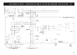
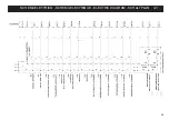
Page 64: ...64 SCHEMA ELETTRICO SCHEMA ELECTRIQUE ELECTRIC DIAGRAM SCHALTPLAN 1...

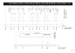
Page 65: ...65 SCHEMA ELETTRICO SCHEMA ELECTRIQUE ELECTRIC DIAGRAM SCHALTPLAN 2...

Page 66: ...66 SCHEMA ELETTRICO SCHEMA ELECTRIQUE ELECTRIC DIAGRAM SCHALTPLAN 3...

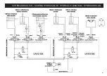
Page 67: ...67 SCHEMA IDRAULICO SCHEMA HYDRAULIQUE HYDRAULIC DIAGRAM HYDRAULIKPLAN...

Page 68: ......

Reviews:

Related manuals for S 560