18
7.5
7.5
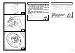
B/4
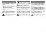
OPERAZIONI PRELIMINARI
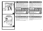
Aprire il portellone del furgone e scaricare la colonnetta mobile porta
comandi e posizionarla lateralmente e al di fuori della sagoma dello
smontagomme.
NOTA:
L'utilizzatore deve provvedere ad una prolunga per il tubo
di scarico, per permettere ai gas del motore di uscire dalla porta
posteriore del furgone (vedi note sul manuale istruzioni del gruppo
generatore). Il costruttore fornisce, in dotazione, due riduzioni da
montare sulla marmitta del motore del gruppo per adattare un even-
tuale tubo di prolunga.
Per portare lo smontagomme in posizione di lavoro occorre:
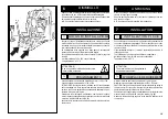
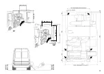
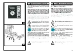
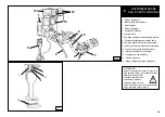
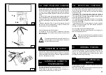
- Avviare il gruppo generatore/compressore utilizzando il quadro (fig.
B/4). Ruotare la chiave in posizione 1 per il riscaldamento, una volta
spenta la spia gialla, ruotare la chiave su 2 per fare avviamento.
B/5
L'operazione di messa in moto del gruppo generatore/
compressore deve essere fatta da personale esperto.
C
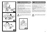
Agendo sulla leva
C
ribaltare lo smontagomme fuori dal furgone fino
al completo appoggio a terra dei piedi stabilizzatori.
Uno di questi piedi è regolabile, in caso di necessità occorre regolarlo,
agendo sulla vite
E
, per ottenere l'appoggio a terra di entrambi i piedi.
Aprire il braccio porta autocentrante agendo sulla leva 8 (fig. C pag.
20)
Montare l'utensile
D
nell'apposito alloggiamento. (fig. B/5)
Prima di utilizzare lo smontagomme accertarsi che sia
posizionato correttamente a terra.
Prima della messa in moto del gruppo elettrogeno è
consigliabile apporre al di fuori del furgone un lampeg-
giante di pericolo arancione.
D
E
Durante l'utilizzo dello smontagomme con gruppo elet-
trogeno avviato e compressore in funzione è
CONSI-
GLIABILE
indossare una protezione antirumore.
PRELIMINARY OPERATIONS
Open the van door and unload the mobile control column and position
it at the side and away from the tyre changer.
NOTE
: The user must prepare an extension pipe for the exhaust, so
that the gas of the motor is expelled from the rear door of the van (see
notes in instruction manual of generator). The manufacturer supplies
two reductions with the machine, which are to be fitted on the exhaust
of the motor of the unit to adapt it to a feasible extension pipe.
To put the tyre changer in the working position:
- start the generator/compressor from the control panel (fig. B/4). Turn
the key to position 1 to warm up; once the yellow LED switches off,
turn the key to position 2 to start it.
The generator/compressor must be started up by an
expert.
Using the lever (
C
) tip the tyre changer outside the van until the
stabiliser feet completely touch the ground.
One of these feet are adjustable so that you can adjust it if necessary,
by turning the screw
E
, so that both feet touch the ground.
Open out the self-centering chuck arm using the lever 8 (fig. C page
20)
Fit the tool (
D
) in the dedicated lodging (fig. B/5).
Before you use the tyre changer, make sure it is posi-
tioned correctly on the ground.
Before you start the generator you are recommended to
put an orange flashing beacon outside the van.
When using the tyre changer with the generator running
and the compressor working, you are
RECOMMENDED
to wear protective headphones.
Summary of Contents for S 561
Page 17: ...15 B 1 Min 1100 mm Min 1600 mm...

