30
13.1
13.1
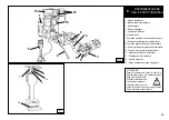
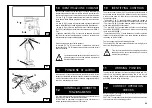
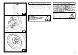
2) Ribaltare in posizione di fuori lavoro il braccio porta-utensili (14,
fig. D).
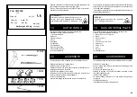
BLOCCAGGIO RUOTA
LOCKING THE WHEEL
USO
13
13
OPERATION
ATTENZIONE !
In fase di bloccaggio assicurarsi che le
griffe siano posizionate in modo corretto
sul cerchione, onde evitare la caduta
della ruota.
WARNING!
In locking the wheel, make sure that
clamps are properly positioned on the
rim, so as to prevent the tyre from
falling
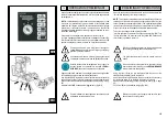
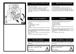
1) Portarsi con la colonnetta mobile in posizione di
lavoro B.
1) Take the mobile control unit to work position B.
2) Pull the tool-holder arm (14, fig. D) out of the working position.
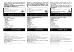
ATTENZIONE !
Questa operazione può essere estremamente pericolosa!
Effettuarla manualmente solo nel caso si sia assolutamente
sicuri di riuscire a mantenere in equilibrio la ruota. Le ruote
non devono mai essere sollevate dall'operatore, si
deve farle rotolare sul pavimento per ruote pesanti
oltre 110 kg e/o di grandi dimensioni (diametro
oltre 130 cm) si DEVE utilizzare un adeguato
mezzo di sollevamento meccanico.
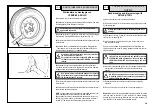
3) Alzare od abbassare il braccio porta-autocentrante fino a centrare
il più possibile l'autocentrante (3, fig. C1) rispetto al cerchio.
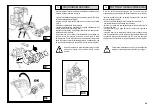
4) Con le griffe (3, fig. C1) in posizione chiusa avvicinare la ruota
all'autocentrante, agire sulla leva (9, fig. C) per aprire l'autocentrante
e bloccare così il cerchio internamente e nella posizione più conve-
niente che va scelta in base al tipo di cerchio, come esemplificato
nelle figure E/1-E/2-E/3-E/4-E/5-E/6.
Si ricorda comunque che il bloccaggio sulla flangia centrale è da
ritenersi sempre il più sicuro.
N.B. : per le ruote con il cerchio a canale bloccare la ruota in modo
che il canale si trovi sul lato esterno (vedi fig. E/1).
DANGER!
This operation can be extremely dangerous. Do it manually
only if you are certain you can keep the wheel balanced.
Heavy tyres (over 110kg) and/or oversize tyres (with diam-
eter over 130cm) shall never be lifted by hand.
Let them roll on floor and lift them by means of
an adequate mechanical lifting device.
3) Raise or lower the self-centering chuck arm until the chuck is
centred with the rim (3 fig. C1).
4) with the jaws (3 fig C1) closed, bring the wheel up to the chuck,
using the joystick (9 fig. C) to open the chuck and thus block the rim
internally and in the best position, which is chosen based on the type
of rim, as per examples in figs. E/1-E/2-E/3-E/4-E/5-E/6.
Always remember that blocking on the central flange is always the
safest way.
NB. For wheels with grooved rim, block the wheel so that the groove
is on the outside (see. Fig. E/1)
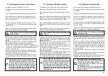
E/2
E/3
E/4
E/5
Summary of Contents for S 561
Page 17: ...15 B 1 Min 1100 mm Min 1600 mm...

