USER MANUAL
DIGITAL READOUT VISION 518
MT02_A31_B_VI518_GIVI_ENG rev. A
Pag. 6/32
INCREMENTAL ENCODER INPUT
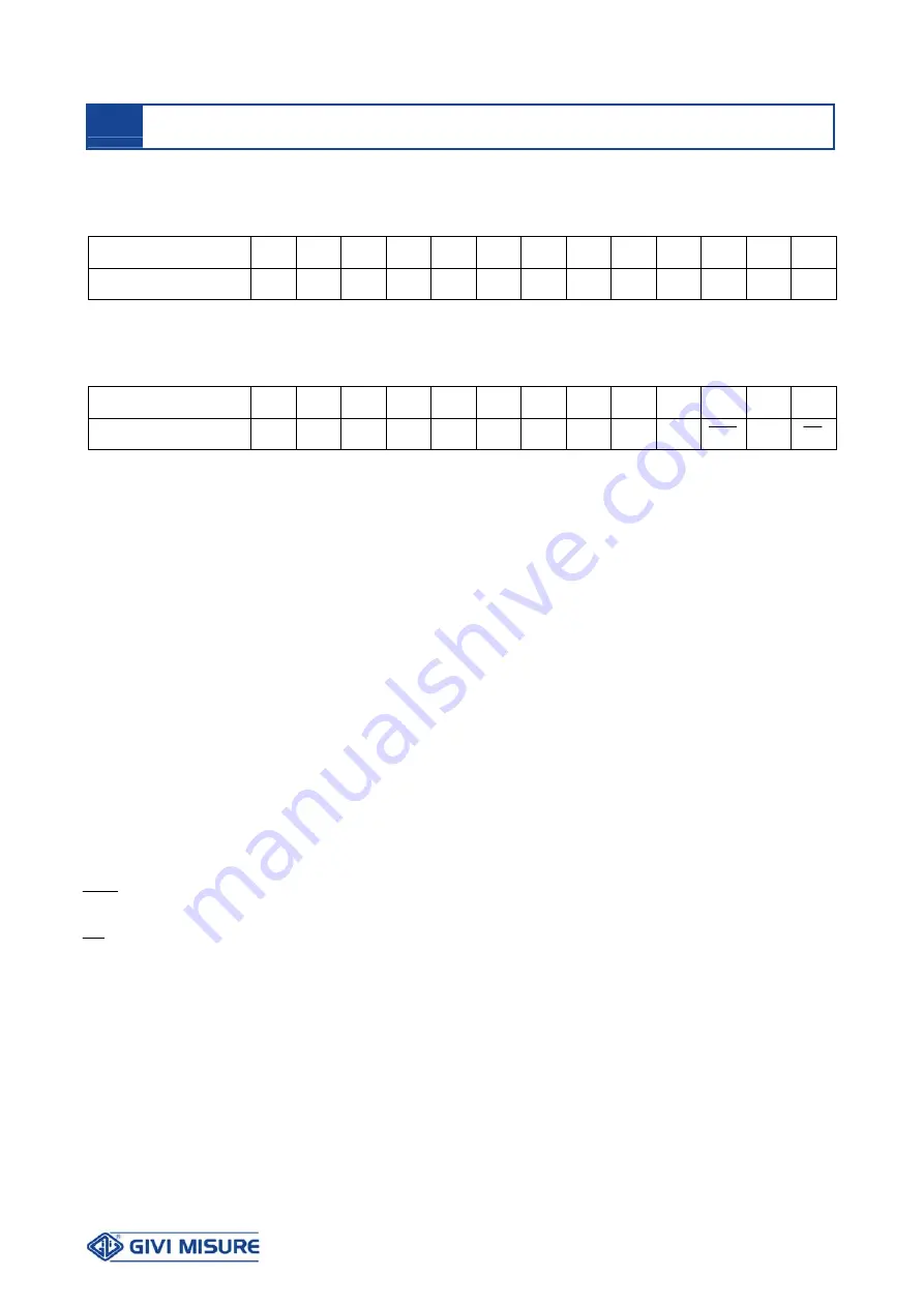
CONNECTIONS
1 2 3 4 5 6 7 8 9 10
11
12
13
TERMINAL BOARD
P.S.
P.S.
C1
NA1
C2
NA2
+ V
0 V
LOAD
QUOTA
/ B A Z
ABSOLUTE (SSI) ENCODER INPUT
CONNECTIONS
1 2 3 4 5 6 7 8 9 10
11
12
13
TERMINAL BOARD
P.S. P.S..
C1
NA1
C2
NA2
+ V
0 V
LOAD
QUOTA
CK
CK
D
D
LEGEND:
P.S.
= Power supply 230 Vac ± 10% 50/60 Hz
(optional 110 Vac 60 Hz – 24 Vac 50/60 Hz)
C1
= Relay 1 common contact
NA1
= N.O. Relay 1 contact
C2
= Relay 2 common contact
NA2
= N.O. Relay 2 contact
+ V
= Encoder power supply output 12 V / 05 V
0 V
= 0 V Encoder power supply
LOAD
= Load position input (connect an N.O. contact between pin 9 and pin 8)
/
= Reserved
B
= Encoder channel B input (for mono-directional sensors, close at 0 V)
A
= Encoder channel A input
Z
= Encoder reference signal input
CK
= SSI absolute encoder clock+ input
CK
= SSI absolute encoder clock- input
D
= SSI absolute encoder data+ input
D
= SSI absolute encoder data- input
Connect the cable’s shield to the ground.
The maximum capacity of the relay contacts is 230 Vac 3A.
CONNECTIONS


