background image

GS-CHR-T5

1 and 2-way LED Remote Starter

FM

2-W

Page 3

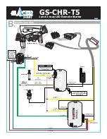
B.

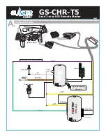
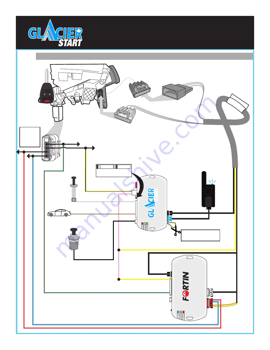
WIRING DIAGRAM

Valet Switch

Hood Pin

Vehicle

Brown/White 

Parking Lights(-)

Yellow/Black - Programmable. 

Set for Ignition using Function 2 

on Page 6.

Pink

Ig)

Gray

Hood Pin(-)

Yellow

Ig)

Yellow

Ig)

EVO-ALL

Cut Yellow Loop when 

installing on an automatic 

transmission

Green/Red

EVO-ALL 6 Pin 

Red Connector

EVO-ALL 5 Pin 

White Connector

Ignition Barrel

THAR-CHR5

PANIC

MUX

2nd Ignition

(+)Starter

(+)12V

If the vehicle 

does not have 

a (+)Starter 

wire, use 

connection A.

White/Blue

White/Red

4 Pin Data Link 

Connector

Antenna

4 Pin Data Link 

Connector

Ensure Jumper on the front 

of the Glacier module is in 

the left(+) position.

+ Polarity

750 mA max

-  Polarity

750 mA max

Summary of Contents for GLC-GS-CHR-T5

Page 1: ...Dodge Chrysler Regular Key GLC GS CHR T5 Installation Guide PANIC ...

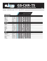
Page 2: ...011 2006 2007 Durango Magnum 2008 2012 2007 2009 2005 2008 2008 Commander Compass 2006 2007 2007 Grand Cherokee Liberty 2005 2007 2008 2012 Patriot Wrangler 2008 2012 2007 2012 2007 2012 L o c k A r m U n l o c k D i s a r m H a t c h o p e n R A P D i s a b l e T r u n k o p e n T a c h o m e t e r D o o r S t a t u s H a n d B r a k e T r u n k S t a t u s C o n n e c t i o n CHRYSLER DODGE JEEP...

Page 3: ...e Parking Lights Pink Ignition Gray Hood Pin Yellow Ignition Yellow Ignition EVO ALL Cut Yellow Loop when installing on an automatic transmission Green Red Purple Wire DO NOT CONNECT ON A JEEP WRANGLER EVO ALL 6 Pin Red Connector EVO ALL 5 Pin White Connector Ignition Barrel THAR CHR5 4 Pin Data Link Connector Antenna ...

Page 4: ...ion EVO ALL Cut Yellow Loop when installing on an automatic transmission Green Red EVO ALL 6 Pin Red Connector EVO ALL 5 Pin White Connector Ignition Barrel THAR CHR5 PANIC MUX 2nd Ignition Starter 12V If the vehicle does not have a Starter wire use connection A White Blue White Red 4 Pin Data Link Connector Antenna 4 Pin Data Link Connector Ensure Jumper on the front of the Glacier module is in t...

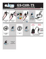
Page 5: ... hold the programming button Insert the remaining connectors EVO ALL Insert the 4 Pin Data Link Connector The LED will alternate between BLUE YELLOW and RED EVO ALL Release the programming button when the LED is Blue If the LED is not solid Blue disconnect the 4 Pin Data Link Connector and go back to step 1 EVO ALL Step 3 I G N Turn the Ignition to the ON Run position O F F Turn the ignition OFF T...

Page 6: ...oor s Open the hood Disengage the parking brake With Neutral Safety Switch Transmission not in neutral position Open the hood Disengage the parking brake Note If the parking lights flash 3 times when remote starting Ready Mode is not enabled Programming Enter Exit Valet Mode I G N Turn Ignition On A B C Insert the key and turn it to the ignition Run On position Within 10 seconds press and release ...

Page 7: ...ock Enabled Arm alarm activate starter kill lock door when the door is closed Starter kill Anti grind Anti Grind only Relay normally open 1st Lock Unlock Silent 2nd Lock Unlock Sound Antenna LED Active Lock Unlock Sound Always Antenna LED Disabled Antenna LED Disabled with ignition 13 14 Sound Confirmation Confirmation Pulse Horn Only Long Short Alarm Starter Options Alarm disabled Remote starter ...

Page 8: ...gnition ON Valet button x4 times and x1 time 3 seconds Ignition ON Valet button x5 times and x1 time 3 seconds Ignition ON Valet button x6 times and x1 time 3 seconds Ignition ON Valet button x7 times and x1 time 3 seconds Ground Out Shut down 1 second after remote start runtime Shut down 3 seconds after remote start runtime Manual Transmission Ready Mode Activation Activated by the remote starter...

Reviews: