background image

- 80 -

Appendix

Features & Peripherals

Color & Material

Gray, Aluminum

GPS

1 x GPS Module with External Antenna (optional)

Mounting 

Compatibility

RAM mount; VESA-75

I/O Ports

2 x USB, 1 x RJ-45, 2 x RS-232, 2 x Audio (1 x Micro-

phone, 1 x Speaker), 1 x DC Plug (bottom side)

Mechanical & Environmental

Operating Temp.

-20 ~ 45°C (-4 ~ 113°F)

Charging Temp.

0 ~ 40°C (32 ~ 104°F)

Storage Temp.

-20 ~ 60°C (-4 ~ 140°F)

Operating Humidity 5 to 95% (non-condensing)
Dimensions  

(W x D x H)

112.4 x 171.3 x 275.1 mm (4.43" x 6.74" x 10.83")

Weight (Net)

1.4 kg (3.1 lb)

Vibration

3 Grms/ 5 ~ 500Hz/ Random operation

Shock

75G peak acceleration (11 ms duration)

Power

Requirement

9 ~ 48V, DC In

The VMC-0720 vehicle mount cradle with optioanl built-in GPS module comes 

in as an accessory option for G0720/G0820. G0720/G0820 can be installed 

on the cradle that can be mounted on a vehicle. The vehicle cradle provides 

extra I/O ports for the rugged PC so that it can be connected to additional 

peripherals. Please go through this chapter to find out more about this vehicle 

cradle.

1.1  Getting Start

1.2  Specifications

Summary of Contents for G0720

Page 1: ...Gladius G0720 G0820 7 8 Intel AtomTM Z530P Rugged Tablet PC User s Manual Version 1 1 P N 4012072000110P 2011 12 ...

Page 2: ... 2 This page is intentionally left blank ...

Page 3: ...ications 4 1 4 Overview 7 1 5 Dimensions 9 1 6 Bar Code Types 11 1 7 Introduction 12 Chapter 2 Installation and Configuration 17 2 1 Getting Start 18 2 2 Battery Replacement 19 2 3 SIM Card Installation 22 2 4 DC Power Supply 23 2 5 Driver Utilities Installation 23 2 5 1 Chipset Driver Installation 23 2 5 2 Audio Driver Installation 26 2 5 3 VGA Graphics Driver Installation 28 2 5 4 LAN Driver Ins...

Page 4: ... 2 1 IDE Configuration 69 3 2 2 Super IO Configuration 70 3 3 Boot Settings 71 3 3 1 Boot Settings Configuration 72 3 3 2 Boot Device Priority 73 3 3 3 Hard Disk Drives 74 3 4 Security 75 3 5 Exit Options 76 Appendix Vehicle Mount Cradle Desktop Stand 79 1 1 Getting Start 80 1 2 Specifications 80 1 3 Overview 81 1 4 Dimensions 83 1 5 Introduction 85 1 5 1 Installing on the Vehicle Mount Cradle 85 ...

Page 5: ...This product has passed the CE test for environmental specifications when shielded cables are used for external wiring We recommend the use of shielded cables This kind of cable is available from ARBOR Please contact your local supplier for ordering information FCC Class B This device complies with Part 15 of the FCC Rules Operation is subject to the following two conditions 1 This device may not ...

Page 6: ...mium hexavalent chromium polybrominated biphenyls PBB and polybrominated diphenyl ethers PBDE in electrical and electronic products Member states of the EU are to enforce by 7 1 2006 ARBOR Technology Corp hereby states that the listed products do not contain unintentional additions of lead mercury hex chrome PBB or PBDB that exceed a maximum concentration value of 0 1 by weight or for cadmium exce...

Page 7: ... cabinet and the touch sensor 10 Remove dirt with a lightly moistened cloth and a mild solvent detergent Then wipe the cabinet with a soft dry cloth 11 The openings on the enclosure are for air convection and protect the equipment from overheating DO NOT COVER THE OPENINGS 12 Position the power cord so that people cannot step on it Do not place anything over the power cord 13 If the equipment will...

Page 8: ...ss of cleaning your devices and peripherals users can also use household items to clean their devices and peripherals Below is a listing of items you may need or want to use while cleaning your devices or peripherals Keep in mind that some components in your device may only be able to be cleaned using a product designed for cleaning that component if this is the case it will be mentioned in the cl...

Page 9: ...Outside the European Union If you wish to dispose of used electrical and electronic products outside the European Union please contact your local authority so as to comply with the correct disposal method Vacuum cleaner Absorb the dust dirt hair cigarette particles and other particles out of the device can be one of the best cleaning methods Over time these items can restrict the airflow in a devi...

Page 10: ...t expressly approved by the guarantee of this device could void the user s authority to operate the equipment Additional Information Technical Support You can download the related technical documents such as datasheet and user s manual as well as driver on our website Please do not hesitate to call or e mail our customer service when you still cannot get the information you need http www arbor com...

Page 11: ...isuse of or inability to use this product Vendor will not be liable for any claim made by any other related party Vendors disclaim all other warranties either expressed or implied including but not limited to implied warranties of merchantability and fitness for a particular purpose with respect to the hardware the accompanying product s manual s and written materials and any accompanying hardware...

Page 12: ... viii This page is intentionally left blank ...

Page 13: ... 1 General Information 1 Chapter 1 General Information Chapter 1 General Information ...

Page 14: ...cessories If any of the above items is damaged or missing contact your vendor immediately 1 x G0720 or G0820 Accessory Package 1 x User s Manual 1 x Driver CD 1 x Power Cord Europe standard cordset 1 x Power Cord American standard cordset 1 x Power Adapter 2 x External Battery Packs 1 1 Packing List ...

Page 15: ...Atom Z530P rugged tablet PC w camera Bluetooth WiFi RFID G0820 8 Intel Atom Z530P rugged tablet PC w camera Bluetooth WiFi Barcode RFID HSUPA G0820 Medium 8 Intel Atom Z530P rugged tablet PC w camera Bluetooth WiFi RFID G0820 Lite 8 Intel Atom Z530P rugged tablet PC w WiFi The following items are normally optional but some vendors may include them as a standard package or some vendors may not carr...

Page 16: ... integrated Memory 2GB DDR2 800 SDRAM Chipset Intel System Controller Hub US15WPT Optional Configuration Configure to Order Service BarC 0720 1D 2D Barcode Scanner Kit HSUPA 0720 3 75G HSUPA Wireless Kit BT 0720 Bluetooth 2 1 Kit CAM 0720 2 0M CMOS Camera Kit RFID 0720 13 56MHz RFID Kit GPS 0720M GPS Kit for G0720 G0820 ...

Page 17: ...M UMTS Gobi 3000 HSUPA module 3 75G for GSM GPRS EDGE networks optional GPS 1 x GPS module Vehicle cradle function optional Barcode Scanner 1 x 1D 2D Barcode Scanner optional Expansion 1 x 35 pin pogo connector for connection with vehicle cradle SIM Socket 1 x SIM socket located underneath the battery pack Hand Strap 1 x Black elastic hand strap Button Indicator Function Key 6 x Function keys 2 x ...

Page 18: ...t 19VDC 3 42A 65W Battery Type Li battery pack Battery Capacity 2 x 2500mAH 3 cell Battery Operating 8 hours Max Mechanical Environmental Operating Temp 0 50ºC 32 122ºF Operating Humidity 5 95 non condensing Dimensions W x D x H 240 x 47 x 188 mm 9 45 x 1 85 x 7 4 Gross Weight 1 7 kg 3 7 lb G0720 1 8 kg 3 9 lb G0820 Vibration 3 Grms 5 500Hz random operation Shock 75G peak acceleration 11 ms durati...

Page 19: ...peaker Power On Off Barcode Scanner Trigger Button Barcode Scanner optional RFID optional Qwerty 61 Key Pad Auto Focus Camera optional Dual External Hot swappable Battery Barcode Scanner Trigger Button RS 232 2 x USB Power Jack 35 pin pogo connector for connection with vehicle cradle Sealed I O ports Sealed I O ports ...

Page 20: ... Speaker Power On Off Barcode Scanner Trigger Button Barcode Scanner Trigger Button RS 232 2 x USB Power Jack 35 pin pogo connector for connection with vehicle cradle Sealed I O ports Sealed I O ports Barcode Scanner optional RFID optional Dual External Hot swappable Battery Auto Focus Camera optional ...

Page 21: ... 9 General Information 1 5 Dimensions 255 203 5 47 5 60 5 188 3 239 8 199 7 Unit mm G0720 ...

Page 22: ... 10 General Information 255 203 5 47 5 60 5 188 3 239 8 199 7 Unit mm G0820 ...

Page 23: ...Code Code 32 QR Code Code 39 Micro QR Code Code 93 and 93i Postal Code 2 of 5 Intelligent Mail Barcode EAN formerly 4 state customer barcode Interleaved 2 of 5 Australian Post Label Code British Post Matrix 2 of 5 Canadian Post MSI ID tag UPU 4 state Plessey Japanese Post PosiCode Netherlands KIX Post GS1 DataBar formerly RSS Korea Post Telepen Planet Code Trioptic Code Postnet UPC OCR Stacked OCR...

Page 24: ... 12 General Information Function Keys Light Sensor Mic Power WiFi Bluetooth Battery Menu Buttons Speaker Qwerty 61 Key Pad G0720 Front Side 1 7 Introduction ...

Page 25: ...n the front panel are available after users have installed the Function Key utility These keys can be defined by users Please refer to Section Function Key for the default value of each function key Should you want to change the settings please select Start Settings Control Panel and then click the Function Key Configure icon to configure the functions of those keys ...

Page 26: ...e Green Charger w Adapter Red Blinking Orange Blinking Green Blinking Green LED Color Status Description Power Green On Power on Off No power WiFi Green On WiFi enabled Off WiFi disabled Bluetooth optional Blue On Bluetooth connection is active Off Bluetooth connection is inactive Battery Green Red On Green Battery fully charged On Red Low battery Blinking Battery is charging To be more specific t...

Page 27: ...ower On Off Barcode Scanner Trigger Button Barcode Scanner Trigger Button Rear Side Auto Focus Camera optional Dual External Hot swappable Battery Power ON OFF the power button used to turn on off the PC must hold the button for about 2 seconds ...

Page 28: ... 16 General Information Top Side RS 232 2 x USB Power Jack Bottom Side Sealed I O ports 35 pin pogo connector for connection with vehicle cradle Barcode Scanner optional RFID optional ...

Page 29: ... 17 Installation and Configuration 2 Chapter 2 Installation and Configuration Chapter 2 Installation and Configuration ...

Page 30: ...efore installing the operating system and driver utilities you should prepare your own USB keyboard and USB CD ROM drive and the power adapter included in the accessory box When the operating system on your computer is ready please use the accompanying Driver CD to install the drivers and utilities for the respective devices The following sections will guide you through the drivers and utilities i...

Page 31: ...alling SIM card please follow the steps below 1 Disconnect the DC power plug and turn off the computer 2 Remove any peripheral devices connected to the computer 3 Press the plastic piece inwards and lift it upwards to remove the battery 4 Push another battery into the right position of battery compartment until you hear a click sound 5 Repeat step 1 to 5 to replace another battery plastic piece ...

Page 32: ... front will turn on steadily in green and then it s recommended to remove the adapter from the computer It s recommended not to recharge intermittently which means not to plug and unplug the power adapter frequently in short period of time It s recommended to turn off the computer before charging Do not use the power adapter that is not made for your computer Supplying the computer with inappropri...

Page 33: ... near fire Don t disassemble the batteries or the battery leakage might cause skin or eye injury If electrolyte leaking from the battery packs contacts your skin or clothing immediately flush it with running water If it splashes into eye rinse the eye at least 15 minutes with clean water and then seek medical attention To avoid battery leakage or explosion don t discard the batteries into water or...

Page 34: ... optional You should prepare a 3G SIM card firstly and remove the Battery 2 in light of steps shown in the beginning of Section Battery Replacement Underneath it is a SIM socket insert your SIM card into the socket as the picture below install the Battery 2 again and then you can start to use its 3G network function 3G SIM card SIM socket ...

Page 35: ...ction Battery Replacement 2 4 DC Power Supply 1 After you put the disk into the CD ROM drive the driver utility installation main menu will jump out automatically Click Chipset of the main menu to install the chipset driver 2 5 1 Chipset Driver Installation 2 5 Driver Utilities Installation Before you install the drivers you must make sure the OS Operating System in this case Windows XP is install...

Page 36: ... 24 Installation and Configuration 2 Make sure you have closed all programs which run behind and then click Next to continue 3 Please read the license agreement first and click Yes to continue ...

Page 37: ... 25 Installation and Configuration 4 Please read the Readme file for system requirements and installation information and click Next to continue 5 Click Finish to complete the setup process ...

Page 38: ... 26 Installation and Configuration 2 5 2 Audio Driver Installation 1 Click Audio of the main menu to install the audio device driver 2 Click Next to continue ...

Page 39: ...initiate the installation 4 After installing the audio device driver you will be asked if you would like to restart the computer It is required to select Yes I want to restart my computer now in order to make sure the program will run properly Then click Finish to proceed ...

Page 40: ...lation and Configuration 1 Click VGA of the main menu to install the device driver 2 5 3 VGA Graphics Driver Installation 2 Make sure you have closed all programs which run behind and then click Next to continue ...

Page 41: ...nstallation and Configuration 3 Please read the license agreement first and click Yes to continue 4 Please read the Readme file for system requirements and installation information and click Next to continue ...

Page 42: ...le for the data extracting and file copying and click Next to continue 6 After installing the graphics device driver click Finish with Yes radio button selected to restart your computer to have the changes take effect or with No to restart this computer later ...

Page 43: ... 31 Installation and Configuration 1 Click LAN of the main menu to install the LAN device driver 2 5 4 LAN Driver Installation 2 Click one of the options and then click Next to continue ...

Page 44: ... 32 Installation and Configuration 4 Click Install to start installation or Back to go back to the previous step 3 Click Next to continue ...

Page 45: ... 33 Installation and Configuration 5 Click Finish to close the wizard window ...

Page 46: ... 34 Installation and Configuration 2 5 5 RS 232 Driver Installation 1 Click RS 232 of the main menu to install the RS 232 device driver 2 Wait for the process ...

Page 47: ... 35 Installation and Configuration 1 Click Touch Screen to install the driver for touch screen 2 When you see the welcome wizard click Next to continue 2 5 6 Touch Screen Driver Installation ...

Page 48: ... 36 Installation and Configuration 3 Click I Agree to continue the installing PenMount Universal Driver 4 Click Browse to change the installation directory or immediately click Install to continue ...

Page 49: ... 37 Installation and Configuration 5 Click Yes to restart your computer to make the new settings take effect or click No to restart your computer later 6 Click Finish to close this wizard ...

Page 50: ... 38 Installation and Configuration 2 Click Next to continue 1 Click Function keys to install the function key configuration utility 2 5 7 Function Key Installation ...

Page 51: ...nfiguration 3 Click Browse to change the installation directory or immediately click Next to continue 4 Select the Start Menu folder in which you would like to create the program s shortcuts and then click Install to continue ...

Page 52: ...s Win XP as background environment However for Win 7 the installation steps are slightly different Please follow these steps Please execute Arbor_toxi_20110826 exe from the following path DVD RW Drive G0720_G0820 R1 1 Function Key Right click the program and select Run as administrator The rest steps are the same as forgoing step 2 5 ...

Page 53: ... 41 Installation and Configuration 1 Click WiFi of the main menu to install the wireless WiFi driver 2 5 8 WiFi Driver Installation 2 Select preferred language ...

Page 54: ... 42 Installation and Configuration 3 Wait for the process 4 Click Next ...

Page 55: ... 43 Installation and Configuration 5 Choose I accept the terms of the license agreement and click Next 6 Select preferred type and Click Next ...

Page 56: ... 44 Installation and Configuration 7 Click Next 8 Click Next ...

Page 57: ... Installation and Configuration 9 Read Important warning and click Next directly 10 Select the first option as previous screenshot recommends since Third Party Supplicant brings some restriction Click Next ...

Page 58: ... 46 Installation and Configuration 13 Choose Yes I want to restart my computer now and click Finish to complete all process 11 Click Yes to reboot later 12 Wait for the process ...

Page 59: ...tion 1 Click Bluetooth of the main menu to install the Bluetooth device driver 2 5 9 Bluetooth Driver Installation optional 3 Check the driver information and click Next to continue 2 Select your preferred language for installation ...

Page 60: ...nfiguration 4 Please read the license agreement first select I accept the terms in the license agreement and then click Next to continue 5 Click Next to install to this folder or click Change to install to a different folder ...

Page 61: ...click Back to go back to the previous step Note A Custom Settings window as the figure below will ask for your preference of whether to set the Bluetooth icon as a shortcut You can choose either Startup shortcut or Desktop shortcut by checking the tickbox at the right hand side ...

Page 62: ...nd then a message box shows up asking whether you want to restart the computer right away or later 1 Click RFID on the main menu to install the RFID application The AP letters on its icon imply this is an application not driver The same principle applies to 3G AP and GPS 2 5 10 RFID AP Installation optional ...

Page 63: ... 51 Installation and Configuration 2 Read the information and then click Next to continue 3 Click Next to install to this folder or click Browse to install to a different folder ...

Page 64: ... 52 Installation and Configuration 4 The application is being installed please wait for a while 5 Click Finish to complete the installation ...

Page 65: ... 53 Installation and Configuration Click 3G of the main menu to install the device driver 2 5 11 3G Driver Installation optional 2 Click Next and the program will do the rest ...

Page 66: ... 54 Installation and Configuration 2 Read the information and click Next 1 Click 3G AP of the main menu to install the application 2 5 12 3G AP Installation optional ...

Page 67: ... 55 Installation and Configuration 3 Read warning and click Next 4 Choose Iacceptthetermsinthelicenseagreement andpressNext Click Change to designate another installation folder if you like ...

Page 68: ... 56 Installation and Configuration 6 Click Finish to complete the installation 5 Wait for the installation ...

Page 69: ... 57 Installation and Configuration 1 Click GPS of the main menu to install the GPS application 2 5 13 GPS AP Installation optional 2 Select a language you prefer ...

Page 70: ... 58 Installation and Configuration 3 Read the information and click Next to continue 4 Read license agreement and click Agree to continue ...

Page 71: ...llation and Configuration 5 Choose the components you need and click Next to continue or check all if you are not sure 6 Click Browse to change the destination directory or immediately click Install to continue ...

Page 72: ...Note The example mentioned above takes Win XP as background environment However for Win 7 the installation steps are slightly different Please execute u center exe from the following path DVD RW Drive G0720_ G0820 R1 1 GPS Right click the program and select Run as administrator The rest steps are the same as forgoing step 2 7 ...

Page 73: ... Installation and Configuration 2 5 14 Function Key 1 After installing function key driver Arbor Tablet UI icon appears in the system tray at the bottom 2 Right click the icon and select Set Function keys ...

Page 74: ...unction or program for each function key from F1 to F6 including Left Right Up Down keys or set program shortcut for each key Since RFID bluetooth and barcode reading function are optional you may set other functions or programs for the original F3 F4 left and right barcode trigger buttons ...

Page 75: ...ate default functions are shown in the table below up down right left F1 Open Close Tablet PC Control UI F2 WiFi on off F3 RIFD on off optional F4 Bluetooth on off optional F5 Brightness down F6 Brightness up Up Key Volume up Down Key Volume down Left Key Barcode scanner optional trigger Right Key Barcode scanner optional trigger ...

Page 76: ...levels inclusive of level 0 2 and 7 5 Keyboard Lock Unlock only for G0720 6 Display rotation on off 7 Bluetooth on off optional 8 RFID on off optional 9 Keyboard LED on off only for G0720 10 Touchscreen on off 11 Wi Fi on off 12 Brightness up 13 Brightness down 14 Volume up 15 Volume down 6 Press F1 and a window will pop up on screen instantly 7 Some of their functions are the same as Function key...

Page 77: ... 65 BIOS 3 Chapter 3 BIOS Chapter 3 BIOS ...

Page 78: ...the power is turned on When the computer is shut down the battery on the motherboard supplies the power for BIOS RAM The Main Setup screen lists the following information System Overview BIOS Version displays the current version information of the BIOS EC Version displays the current version of Embedded Controller Build Date the date that the BIOS version was made updated Processor auto detected i...

Page 79: ... a message screen will display and ask you to select OK or Cancel for exiting and discarding changes Use and to select and press Enter to confirm On the Sub Menu Exit current page and return to main menu Page Up Increase the numeric value on a selected setup item make change Page Down Decrease the numeric value on a selected setup item make change F1 Activate General Help screen F10 Save the chang...

Page 80: ... RFID BT Bluetooth CCD and Light Sensor etc Touch GSensor WLAN RFID BT CCD Light Sensor Configuration PPM C6 Support Attention even though you set these configurations as enable or disable after entering into OS they still work according to Function Key setting described in Section Function Key instead of the configurations in BIOS Setup Utility here Enable Disable to save more power ...

Page 81: ... 69 BIOS 3 2 1 IDE Configuration When entering the setup BIOS automatically detects the presence of IDE devices This item shows status of auto detected IDE devices and allows you to configure subitems ...

Page 82: ... 70 BIOS 3 2 2 Super IO Configuration Configure Addresses IRQs for Serial Port1 4 ...

Page 83: ...71 BIOS 3 3 Boot Settings This item allows you to set your device s booting preferences There are to tally three submenus in it including Boot Settings Configuration Boot Device Priority Hard Disk Drives ...

Page 84: ... When it is enabled the BIOS will display the full screen logo during the boot up sequence hiding normal POST messages When it is disabled the BIOS will display the normal POST messages instead of the full screen logo Bootup Num Lock Wait For F1 If Error This setting determines whether the Num Lock key should be activated at boot up To enable waiting for F1 key to be pressed if error occurs ...

Page 85: ... 73 BIOS This setting determines the priority that the BIOS uses to look for a boot device from which the operating system is loaded during the DOS boot process 3 3 2 Boot Device Priority ...

Page 86: ... 74 BIOS This function displays the information of HDD detected Through it you can also set boot sequence from available HDD detected 3 3 3 Hard Disk Drives ...

Page 87: ...ar at the center of the screen to assist you in creating a password Enter New Password Type the password up to six characters in length and press Enter The password typed now will clear any previously entered password from CMOS memory You will be asked to confirm the password Type the password again and press Enter You may also press ESC to abort the selection and not enter a password ...

Page 88: ...ny part of your system configuration You can also have the BIOS request a password every time your system is rebooted by setting it to Always This would prevent unauthorized use of your computer To clear the password just leave the field blank and press Enter when you are prompted to enter a new password Once the password is cleared the following message will appear at the center of the screen Pas...

Page 89: ...S will configure your system according to the Setup selections stored in CMOS After saving the values by clicking OK the system is going to restart again Save Changes and Exit Discard Changes and Exit Exit system setup without saving any changes Click OK to confirm Load Optimal Defaults When you press Enter on this item you get a confirmation dialog box con taining a message as below Load Optimal ...

Page 90: ... 78 This page is intentionally left blank ...

Page 91: ... 79 Appendix Appendix Vehicle Mount Cradle Desktop Stand Appendix Vehicle Mount Cradle Desktop Stand ...

Page 92: ...imensions W x D x H 112 4 x 171 3 x 275 1 mm 4 43 x 6 74 x 10 83 Weight Net 1 4 kg 3 1 lb Vibration 3 Grms 5 500Hz Random operation Shock 75G peak acceleration 11 ms duration Power Requirement 9 48V DC In The VMC 0720 vehicle mount cradle with optioanl built in GPS module comes in as an accessory option for G0720 G0820 G0720 G0820 can be installed on the cradle that can be mounted on a vehicle The...

Page 93: ...inge pressing bar pressing bar 2 x RS 232 ports DC Plug speaker microphone the outer four VESA 75 holes consisting a square may connect to Desktop Stand see next page the inner four screw holes consisting a square may connect to a RAM ball RJ 45 port 35 pin POGO connector 35 pin POGO connector GPS antenna ...

Page 94: ... 82 Appendix Desktop Stand ...

Page 95: ... 83 Appendix 267 5 171 9 82 63 113 4 91 3 280 3 113 4 148 4 1 4 Dimensions Unit mm Vehicle Mount Cradle ...

Page 96: ... 84 Appendix Desktop Stand Unit mm ...

Page 97: ...n this section to install the G0720 G0820 rugged PC on the docking station 1 When placing the rugged PC onto the vehicle cradle please do it from a slanted direction 1 5 Introduction 2 Make sure you align the 35 pin POGO connectors on both the rugged PC and the cradle together K hook ...

Page 98: ... 86 Appendix 3 Once the rugged PC has been correctly positioned on the vehicle cradle flip the k hook so that its claws can firmly catch on two square pits on the top of rugged PC ...

Page 99: ... 87 Appendix 1 5 2 Removing from the Vehicle Mount Cradle To remove the rugged PC from its cradle use your thumb to press the metal bar and lift up the k hook ...

Page 100: ...line attached with the cradle Another end shown above is connected to the vehicle power supply unit Screw the GPS antenna connected with the cradle itself on the SMA jack to acti vate optional GPS module Use a DB 9 female connector D Sub to plug into the COM port to connect with serial de vices such as modem console devices or data gateway Plug a LAN cable in RJ 45 type to the LAN port for connect...

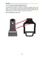
Page 101: ... further mounted to a desktop stand via the VESA 75 x 75 compliant screw holes at the back With desktop stand you can put the cradle on a surface steadily since its bottom is not flat Please take the images below as a reference for how to align the screw holes Recommended screw size M4 ...

Reviews: