background image


7179750301 / Index 06 

12.02.2020 

Seite 5 von 29 

de 

en 

fr 

tr 

el 

es 

pt 

da 

nl 

no 

sv 

pl 

cs 

hu 


Bedeutungen in der Betriebsanleitung 

Zum besseren Verständnis sollen die folgenden Vereinbarungen für die 
Betriebsanleitung getroffen werden: 

1. 

Um wichtige Informationen hervorzuheben, werden zwei Arten besonderer 
Hinweise verwendet: 

Dieses Zeichen ist neben allen Warnhinweisen zu finden, die im Fließtext 
auffallen sollen. Zudem ist der Text, wie hier, fett gedruckt. Diese Art von 
Warnhinweis bedeutet, dass Gefahr für Leben und Gesundheit von 
Personen besteht. Beachten Sie diese Hinweise besonders und verhalten 
Sie sich in allen diesen Fällen äußerst vorsichtig, um sich vor Verletzungen 
zu schützen.  

Andere Warnhinweise sind umrahmt dargestellt. Hier geht es um die 
Vermeidung von Sachschäden. Auch diese Hinweise müssen unbedingt 
beachtet werden. 

2. 

Manche Texte dienen einem besonderen Zweck. Diese werden folgendermaßen 
gekennzeichnet: 

 Aufzählungen. 


Anleitender Text, z.B. eine Abfolge von Tätigkeiten. 


Summary of Contents for FX60

Page 1: ...6 12 02 2020 Seite 1 von 29 de en fr tr el es pt da nl no sv pl cs hu Explosionsgeschützter Strahler mit LED Betriebsanleitung FX60 Glamox Marine and Offshore GmbH Linzer Straße 9a 28359 Bremen Germany www glamox com gmo ...

Page 2: ...20 7179750301 Index 06 de en fr tr el es pt da nl no sv pl cs hu Die Betriebsanleitung ist vor Einsatz des Produktes sorgfältig zu lesen GLAMOX BEHÄLT SICH VOR AN DEN BESCHRIEBENEN PRODUKTEN TECHNISCHE ÄNDERUNGEN VORZUNEHMEN ...

Page 3: ...ie 94 9 EG 9 Sicherheitsaufkleber 10 Produktbeschreibung 10 Allgemeines 10 Hauptkomponenten 11 Betrieb 11 Installation 12 Zulässige Anbaulagen 13 Befestigung 13 Kabelverschraubungen 14 Strahler anschließen 15 Handhabung der Anschlussklemme 17 Externer Potentialleiter 18 Stranginstallation 18 Wartung und Instandsetzung 19 Besondere Sicherheitsvorschriften 19 Reinigung 19 Wartung 19 Störungsbeseitig...

Page 4: ...ondere die Sicherheitshinweise Diese Betriebsanleitung gilt nur für die unter Abschnitt Bestellnummern angegebenen Produkte Bewahren Sie die Betriebsanleitung nach dem ersten Durcharbeiten gut auf damit Sie später einmal etwas nachschlagen können Alle Angaben Abbildungen und Maße dieser Betriebsanleitung sind unverbindlich Ansprüche jeglicher Art können daraus nicht abgeleitet werden Nachdruck und...

Page 5: ...xt auffallen sollen Zudem ist der Text wie hier fett gedruckt Diese Art von Warnhinweis bedeutet dass Gefahr für Leben und Gesundheit von Personen besteht Beachten Sie diese Hinweise besonders und verhalten Sie sich in allen diesen Fällen äußerst vorsichtig um sich vor Verletzungen zu schützen Andere Warnhinweise sind umrahmt dargestellt Hier geht es um die Vermeidung von Sachschäden Auch diese Hi...

Page 6: ... sich auf grob fahrlässige bzw vorsätzliche Vertragsverletzung zurückführen Der Hersteller kann nicht jede Gefahr voraussehen Die in diesen Hinweisen enthaltenen und an dem Produkt angebrachten Warnungen schließen deshalb unter Umständen nicht alle Gefahren ein Neben den Hinweisen in dieser Betriebsanleitung müssen die Vorschriften des Gesetzgebers berücksichtigt werden insbesondere die Sicherheit...

Page 7: ...itere Arbeit einfließen lassen Kontaktaufnahme siehe Kapitel Kundendienst Anforderungen an das Personal Nicht qualifiziertem Personal ist das Arbeiten an dem explosionsgeschützten Strahler untersagt Der Umgang mit dem explosionsgeschützten Strahler ist nur Mitarbeitern gestattet die im Umgang mit dem explosionsgeschützten Strahler unterwiesen wurden die über die damit verbundenen Gefahren unterric...

Page 8: ... Diese Einrichtungen dürfen nur für Wartungs und Instandsetzungsarbeiten demontiert werden Nach Abschluss dieser Arbeiten müssen die Sicherheits und Schutzeinrichtungen sofort wieder montiert werden Wartungs und Instandsetzungsarbeiten dürfen nur von autorisiertem Fachpersonal nach der Trennung von der Energieversorgung durchgeführt werden Die Durchführung von vorgegebenen Wartungs und Instandsetz...

Page 9: ...gungen sichtbar werden Nur Originalersatzteile und vom Hersteller freigegebenes Zubehör verwenden Bei der Verwendung anderer Teile entfällt die Haftung für die daraus entstehenden Folgen Kennzeichnung gem Richtlinie 2014 34 EU An diesem Strahler wurden mehrere Geräte im Sinne der Richtlinie 2014 34 EU verbaut Das sind im einzelnen folgende Bauteile oder Baugruppen Strahlermodul Anschlussdose Kabel...

Page 10: ...wenden Sie sich an den Kundendienst Aufkleber Bedeutung und Position ALLGEMEINER HINWEIS Für alle Arbeiten und den Betrieb des Moduls ist die Betriebsanleitung zu beachten Position auf der Anschlussdose OPTISCHE STRAHLUNG Direktes Betrachten der LED kann eine Gefahr für das menschliche Auge bedeuten Gemäß EN 62471 2008 ist der Strahler in Gefahrengruppe 1 eingestuft Position am Modulhalter Tabelle...

Page 11: ... nichtrostender Stahl Gehäuse LED Modul Material Seewasserbeständige Aluminiumgusslegierung eloxiert Lampenabdeckung Material Thermisch gehärtetes Floatglas Leuchtmittel LED Betriebsgerät Eigenentwickeltes Betriebsgerät Kabelverschraubungen Zugelassene Kabelverschraubungen der Zündschutzart Ex e bzw Ex d Anschlussklemmen Zugelassene Anschlussklemmen der Zündschutzart Ex e Anschlussdose Zugelassene...

Page 12: ...rung vorgesehen die die Leistung bei Erreichen fest definierter Temperaturen reduziert Die Schaltwerte wurden im Hinblick auf eine optimale Lebensdauer der LED festgelegt Bei Abfall der Temperatur wird die Leistung wieder angehoben Temperatur Leistung Anstieg auf 75 C 50 Anstieg auf 85 C 25 Abfall auf 80 C 50 Abfall auf 70 C 100 Tabelle 2 Temperatursteuerung Installation WARNUNG NICHT UNTER SPANNU...

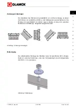
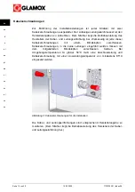
Page 13: ...ärme oder Kältequellen auszuschließen ist Die Montage ist ausschließlich in solchen Lagen zulässig in denen die einzelnen Module wie in Abbildung 1 dargestellt ausgerichtet sind Abbildung 1 Zulässige Anbaulagen Befestigung Die vibrationsfeste Montage des Strahlers muss mit zwei Bolzen M12 erfolgen Dabei ist unter die Mutter bzw unter den Schraubenkopf eine Unterlegscheibe ISO 7093 12 zu montieren ...

Page 14: ...ig ist jede dieser Kabelverschraubungen mit einem Blindstopfen verschlossen Kabelverschraubungen in die keine Leitungen eingeführt werden müssen mit dem mitgelieferten Blindstopfen verschlossen bleiben Bei Umgebungstemperaturen ta größer 50 C muß eine Anschlussleitung und Kabelverschraubung mit einer Anwendungstemperatur von mindestens 85 C eingesetzt werden Abbildung 3 Kabelverschraubungen für di...

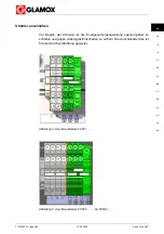
Page 15: ...hu Strahler anschließen Vor Beginn der Arbeiten ist die Energieversorgungsleitung spannungsfrei zu schalten und gegen unbefugtes Einschalten zu sichern Die Anschlussklemme ist für eine Durchverdrahtung geeignet Abbildung 4 Anschlussklemme FX601 Abbildung 5 Anschlussklemme FX602 bis FX604 ...

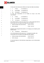
Page 16: ...mstellen 1 bis 3 kann jeweils max 1 Leiter geklemmt werden Die Anschlussklemme ist für folgende Leitungsquerschnitte geeignet flexible Leitungen ohne Aderendhülse 0 5 bis 6 0 mm starre Leitungen 0 5 bis 6 0 mm Zusätzlich stehen folgende Klemmstellen zur Verfügung die bei Bedarf genutzt werden können PE Schutzleiter Klemmstellen 4 An den Klemmstellen 4 kann jeweils max 1 Leiter geklemmt werden Die ...

Page 17: ... Eindrähtige Leitungen lassen sich ohne die Verwendung von Werkzeug kontaktieren Abbildung 6 Kontaktieren ohne die Verwendung von Werkzeug Mehrdrähtige Leitungen oder Leitungen mit kleinen Aderquerschnitten lassen sich unter Verwendung eines Schraubendrehers kontaktieren Abbildung 7 Kontaktieren mittels Schraubendrehers ...

Page 18: ...für eine Durchverdrahtung ausreichender Anzahl an Klemmstellen ausgestattet Somit besteht die Möglichkeit der Installation in einem Strang In der Anschlussdose entsteht durch die eingeführten Leitungen und die Übergangswiderstände an Klemmstellen Wärme Damit die maximal zulässige Temperatur in der Anschlussdose nicht überschritten wird dürfen die eingeführten Anschlussleitungen nur begrenzt belast...

Page 19: ... herstellen kann Nach Wartungs und Instandsetzungsarbeiten alle Sicherheits und Schutzeinrichtungen sofort wieder ordnungsgemäß montieren oder schließen Vor der Wartung unbedingt auch die Hinweise im Kapitel Sicherheit lesen Reinigung Eine besondere Pflege ist grundsätzlich nicht notwendig Das Gehäuse und die Lampenabdeckung sollte gelegentlich mit einem feuchten Tuch gereinigt werden WARNUNG REIN...

Page 20: ...rgehen Wenn diese keine Abhilfe schaffen kann an den Kundendienst wenden Oftmals sind Störungen auf einen fehlerhaften Anschluss oder Wartung zurückzuführen Die Angaben in diesen Abschnitten sind unbedingt zu beherzigen Störung Mögliche Ursache Maßnahmen Strahler leuchtet nicht Hauptnetz oder Hauptsicherung ausgefallen Hauptnetz oder Hauptsicherung einschalten Strahler oder einzelne Module leuchte...

Page 21: ...Linzer Straße 9a 28359 Bremen Germany E mail info productiongermany glamox com Internet www glamox com gmo Technische Daten Leuchtmittel LED Nennleistung FX601 max 40 W FX602 max 80 W FX603 max 120 W FX604 max 160 W Leistungsfaktor 0 95 Nennstrom FX6010 max 0 18 A FX6011 max 0 35 A FX6012 max 0 16 A FX6013 max 0 35 A FX6020 max 0 36 A FX6021 max 0 70 A FX6022 max 0 32 A FX6023 max 0 70 A FX6030 ma...

Page 22: ... EN 60598 UV beständig ja Seewasserbeständig ja Vibrationsgeprüft ja Umgebungstemperatur LED weiß 50 C 55 C Umgebungstemperatur LED bunt 50 C 50 C Gewicht FX601 6 2 kg FX602 12 0 kg FX603 15 7 kg FX604 18 5 kg Ex Kennzeichung der LED Module II 2 G Ex db op is IIC T4 Gb IBExU 13 ATEX 1025 Ex db op is IIC T4 Gb IECEx IBE 13 0025 der LED Strahler II 2 G Ex db eb op is IIC T4 Gb IBExU 14 ATEX 1041 X E...

Page 23: ... FX60200XXX FX60201XXX FX60202XXX 120 V FX60210XXX FX60211XXX FX60212XXX 254 V FX60220XXX FX60221XXX FX60222XXX 115 V FX60230XXX FX60231XXX FX60232XXX 230 V FX60300XXX FX60301XXX FX60302XXX 120 V FX60310XXX FX60311XXX FX60312XXX 254 V FX60320XXX FX60321XXX FX60322XXX 115 V FX60330XXX FX60331XXX FX60332XXX 230 V FX60400XXX FX60401XXX FX60402XXX 120 V FX60410XXX FX60411XXX FX60412XXX 254 V FX60420XX...

Page 24: ...te 24 von 29 12 02 2020 7179750301 Index 06 de en fr tr el es pt da nl no sv pl cs hu Abmessungen Abbildung 9 Explosionsgeschützter Strahler Typ FX601 Abbildung 10 Explosionsgeschützter Strahler Typ FX602 ...

Page 25: ...7179750301 Index 06 12 02 2020 Seite 25 von 29 de en fr tr el es pt da nl no sv pl cs hu Abbildung 11 Explosionsgeschützter Strahler Typ FX603 Abbildung 12 Explosionsgeschützter Strahler Typ FX604 ...

Page 26: ...26 von 29 12 02 2020 7179750301 Index 06 de en fr tr el es pt da nl no sv pl cs hu Ersatzteilnummern Abbildung 13 Ersatzteilnummern für Strahler Typ FX601 Abbildung 14 Ersatzteilnummern für Strahler Typ FX602 ...

Page 27: ...7179750301 Index 06 12 02 2020 Seite 27 von 29 de en fr tr el es pt da nl no sv pl cs hu Abbildung 15 Ersatzteilnummern für Strahler Typ FX603 Abbildung 16 Ersatzteilnummern für Strahler Typ FX604 ...

Page 28: ...Seite 28 von 29 12 02 2020 7179750301 Index 06 de en fr tr el es pt da nl no sv pl cs hu Anziehdrehmomente Größe Anzieh drehmoment Modul M6 7 Nm Strahler am Halter M10 35 Nm Strahler M12 60 Nm ...

Page 29: ... en fr tr el es pt da nl no sv pl cs hu Größe Anzieh drehmoment Deckel für Anschlussdose M6 7 Nm Anschlussdose M6 7 Nm Potentialleiter M6 7 2 Tabelle 7 Anziehdrehmomente für Befestigungsschrauben EU Konformitätsbestätigung siehe Zeichnung 94200114800 ...

Page 30: ... 12 02 2020 Seite 1 von 29 de en fr tr el es pt da nl no sv pl cs hu Explosion proof floodlight with LED Operating instructions FX60 Glamox Marine and Offshore GmbH Linzer Straße 9a 28359 Bremen Germany www glamox com gmo ...

Page 31: ... 2020 7179750301 Index 06 de en fr tr el es pt da nl no sv pl cs hu The operating instructions must be read carefully before using the product GLAMOX RESERVES THE RIGHT TO MAKE TECHNICAL CHANGES TO THE DESCRIBED PRODUCTS ...

Page 32: ...10 Product desription 10 Generel 10 Main components 11 Operation 11 Installation 12 Permissible installation positions 13 Mechanical attachment 13 Threaded cable glands 14 Floodlight connection 15 Handling the connection terminal 17 External potential conductor 18 In line installation 18 Maintenance and Repair 19 Special safety regulations 19 Cleaning 19 Maintenance 19 Troubleshooting 20 Customer ...

Page 33: ...notes These operating instructions only apply for the products indicated under the order numbers section Keep the operating instructions in a safe place after reading through them so that you can consult them again later All data figures and dimensions in these operating instructions are not binding Claims of any nature cannot be derived from these Reprinting and duplication of any type also in ex...

Page 34: ...tes that are to be indicated in plain text The text is also printed bold as here This type of warning note indicates a hazard for the life and health of persons Pay particular at tention to these notes and proceed with extreme caution in all these cases in order to protect yourself from injuries Other warning notes are shown framed These involve the avoidance of material damage These notes must al...

Page 35: ... product unless this damage is due to grossly negligent or deliberate breach of contract The manufacturer cannot foresee every hazard The warnings contained in these notes and attached to the product might not therefore cover all hazards Besides the notes in these operating instructions the regulations of the legislator must be taken into consideration in particular safety and accident prevention ...

Page 36: ...rther work Contact See chapter on Customer Service Requirements for the personnel Unqualified persons are prohibited from working on the explosion proof floodlight Only employees are permitted to work with the explosion proof floodlight who have been instructed in working with the explosion proof floodlight who have been instructed about the associated risks who have been authorized by the operato...

Page 37: ...major risk of injury Maintenance and repair work may only be carried out by authorized technical personnel after disconnecting the power supply Implementation of the specified maintenance and repair work is part of the intended use of the explosion proof floodlight in particular compliance with the maintenance intervals If you do not carry out this work fault free func tioning cannot be guaranteed...

Page 38: ...everal devices as defined by the Directive 2014 34 EU have been installed in this floodlight These are the following components or assemblies individually Floodlight module Junction box Threaded cable gland These components or assemblies are labeled as defined by the Directive 2014 34 EU The labeling is attached either directly or in the form of a rating plate and must always be visible and legibl...

Page 39: ... Service Label Meaning and position GENERAL NOTE The operating instructions must be followed for all work on and operation of the module Position on the heat sink OPTICAL RADIATION Looking directly into the LED can entail a hazard for the human eye According to EN 62471 2008 the floodlight is classified in hazard group 1 Position on the heat sink Table 1 Safety labels Product desription Generel Th...

Page 40: ...istant stainless steel Housing LED module Material Seawater resistant aluminium cast alloy anodized Lamp cover Material Thermally hardened soda lime glass Lamp LED Operating device Own developed operating device Threaded cable glands Approved threaded cable glands of ignition protection type Ex e or Ex d Connection terminals Approved connection terminals of ignition protection type Ex e Junction b...

Page 41: ...ture control is provided which reduces the power upon reaching fixed defined temperatures The switching values in respect to an optimum service life of the LED are defined The power is increased again if the temperature drops Temperature Power Rise to 75 C 50 Rise to 85 C 25 Drop to 80 C 50 Drop to 70 C 100 Table 2 Temperature control Installation WARNING DO NOT OPEN WHEN LIVE Life threatening ele...

Page 42: ... the effects of additional heat or cold sources can be excluded The assembly is only permissible in those positions in which the individual modules are aligned as shown in Figure 1 Figure 1 Permissible installation positions Mechanical attachment The vibration proof attachment has to be done by two bolts M12 with washer acc to ISO 7093 12 under the nut and accordingly screw Figure 2 Mechanical att...

Page 43: ...e floodlight Each of these threaded cable glands is closed with a blind plug at the factory Threaded cable glands into which no lines are introduced must be closed with the blind plug provided At ambient tem peratures ta greater than 50 C a connecting cable and cable gland with an ap plication temperature of at least 85 C must be used Figure 3 Threaded cable glands for installation The line and ca...

Page 44: ...no sv pl cs hu Floodlight connection Disconnect the power supply line and secure against unauthorized reactivation before beginning the work The connection terminal is suitable for through wiring Figure 4 Connection terminal FX601 Figure 5 Connection terminal FX602 to FX604 ...

Page 45: ...ve earth conductor Terminal points 3 Max 1 conductor can be connected at the terminal points 1 to 3 The connec tion terminal is suitable for the following line cross sections Flexible lines without wire end sleeve 0 5 to 6 0mm Rigid lines 0 5 to 6 0mm The following terminal points are also available for use if required PE Protective earth conductor Terminal points 4 Max 1 conductor can be connecte...

Page 46: ...v pl cs hu Handling the connection terminal Single wire lines can be contacted without using a tool Figure 6 Contacting without using a tool Multiple wire lines or lines with small wire cross sections can be contacted using a screwdriver Figure 7 Contacting using a screwdriver ...

Page 47: ...uctor connection In line installation This floodlight is configured with two cable entries and connection terminals sufficient for through wiring Therefore in line installation is possible Cables and contact resistances cause heat inside the connection box To hold the temperture within the permissable termperature range the current has to be limited The value of the current can be taken from the t...

Page 48: ...y can restore the power supply After maintenance and repair work immediately mount or close all safety and protection facilities again Also read the notes in the Safety chapter before maintenance Cleaning Special care measures are not necessary as a rule The housing and lamp cover should occasionally be cleaned with a damp cloth WARNING CLEANING ONLY WITHOUT SOLVENT Risk of explosion Cleaning agen...

Page 49: ...ot provide any remedy contact the Customer Service Malfunctions are often caused by a defective connection or maintenance The da ta in this section must be strictly observed Malfunction Possible cause Measures Floodlight does not light up Main power supply or main fuse has failed Switch on main power supply or main fuse Floodlight or individual modules do not light up Temperature fuse in the modul...

Page 50: ...ffshore GmbH Linzer Straße 9a 28359 Bremen Germany E mail info productiongermany glamox com Internet www glamox com gmo Technical Data Lamp LED Power FX601 max 40 W FX602 max 80 W FX603 max 120 W FX604 max 160 W Power factor 0 95 Power consumption FX6010 max 0 18 A FX6011 max 0 35 A FX6012 max 0 16 A FX6013 max 0 35 A FX6020 max 0 36 A FX6021 max 0 70 A FX6022 max 0 32 A FX6023 max 0 70 A FX6030 m...

Page 51: ...s per EN 60598 UV resistant Yes Seawater resistant Yes Vibration tested Yes Ambient temperature LED white 50 C 55 C Ambient temperature LED colore 50 C 50 C Weight FX601 6 2 kg FX602 12 0 kg FX603 15 7 kg FX604 18 5 kg Ex marking der LED Module II 2 G Ex db op is IIC T4 Gb IBExU 13 ATEX 1025 Ex db op is IIC T4 Gb IECEx IBE 13 0025 der LED Floodlight II 2 G Ex db eb op is IIC T4 Gb IBExU 14 ATEX 10...

Page 52: ...0200XXX FX60201XXX FX60202XXX 120 V FX60210XXX FX60211XXX FX60212XXX 254 V FX60220XXX FX60221XXX FX60222XXX 115 V FX60230XXX FX60231XXX FX60232XXX 230 V FX60300XXX FX60301XXX FX60302XXX 120 V FX60310XXX FX60311XXX FX60312XXX 254 V FX60320XXX FX60321XXX FX60322XXX 115 V FX60330XXX FX60331XXX FX60332XXX 230 V FX60400XXX FX60401XXX FX60402XXX 120 V FX60410XXX FX60411XXX FX60412XXX 254 V FX60420XXX FX...

Page 53: ...Page 24 of 29 12 02 2020 7179750301 Index 06 de en fr tr el es pt da nl no sv pl cs hu Dimensions Figure 9 Explosion proof floodlight type FX601 Figure 10 Explosion proof floodlight type FX602 ...

Page 54: ...7179750301 Index 06 12 02 2020 Page 25 of 29 de en fr tr el es pt da nl no sv pl cs hu Figure 11 Explosion proof floodlight type FX603 Figure 12 Explosion proof floodlight type FX604 ...

Page 55: ... of 29 12 02 2020 7179750301 Index 06 de en fr tr el es pt da nl no sv pl cs hu Spare part numbers Figure 13 Spare part numbers for floodlight type FX601 Figure 14 Spare part numbers for floodlight type FX602 ...

Page 56: ...7179750301 Index 06 12 02 2020 Page 27 of 29 de en fr tr el es pt da nl no sv pl cs hu Figure 15 Spare part numbers for floodlight type FX603 Figure 16 Spare part numbers for floodlight type FX604 ...

Page 57: ...Page 28 of 29 12 02 2020 7179750301 Index 06 de en fr tr el es pt da nl no sv pl cs hu Tightening torques Size Tightening torque Module M6 7 Nm Floodlight on holder M10 35 Nm Floodlight M12 60 Nm ...

Page 58: ... de en fr tr el es pt da nl no sv pl cs hu Size Tightening torque Cover for junction box M6 7 Nm Junction box M6 7 Nm Potential conductor M6 7 2 Table 7 Tightening torques for fastening screws Declaration of Conformity see Drawing No 94200114800 ...

Page 59: ...6 12 02 2020 Página 1 de 29 de en fr tr el es pt da nl no sv pl cs hu Refletor à prova de explosão com LED Manual de instruções FX60 Glamox Marine and Offshore GmbH Linzer Straße 9a 28359 Bremen Germany www glamox com gmo ...

Page 60: ... 2020 7179750301 Índice 06 de en fr tr el es pt da nl no sv pl cs hu Antes de usar o produto deve ler com atenção o manual de instruções GLAMOX RESERVA SE O DIREITO DE PROCEDER A ALTERAÇÕES TÉCNICAS NOS PRODUTOS DESCRITOS ...

Page 61: ... 10 Descrição do produto 10 Generalidades 10 Componentes principais 11 Funcionamento 11 Instalação 12 Posições de montagem autorizadas 13 Fixação 13 Conectores de cabo 14 Ligar refletor 15 Manuseamento do terminal de ligação 17 Condutor potencial externo 18 Instalação da cablagem 18 Manutenção e reparação 19 Prescrições especiais de segurança 19 Limpeza 19 Manutenção 19 Resolução de falhas 20 Apoi...

Page 62: ...plica aos produtos indicados na secção Números de encomenda Guarde este manual de instruções mesmo depois da primeira utilização para o poder voltar a consultar mais tarde As informações imagens e medidas neste manual de instruções não são vinculativas Daí não se podem fazer reivindicações de qualquer tipo A reimpressão e reprodução sejam de que modo forem mesmo só de extratos requerem o consentim...

Page 63: ...recer no texto corrido Além disso o texto aparece a negrito tal como aqui Este tipo de alerta significa que existe perigo para a vida e a saúde de pessoas Observe em particular estas indicações e nestes casos tenha um comportamento extremamente cuidadoso para se proteger contra ferimentos Há outras alertas que são apresentadas com um quadro à volta Aqui trata se de evitar danos materiais Também es...

Page 64: ...s deliberadas ou gravemente negligentes ao contrato O fabricante não consegue prever todo o tipo de perigo Os avisos incluídos nestas indicações e colocados no produto podem por isso não incluir todo o tipo de perigos Para além das indicações neste manual de instruções devem ser ainda observadas as prescrições do legislador sobretudo as prescrições sobre segurança e prevenção de acidentes Utilizaç...

Page 65: ...alho futuro Estabelecer contacto ver Capítulo Apoio ao Cliente Requisitos ao pessoal Pessoal não habilitado não está autorizado a trabalhar no refletor à prova de explosão O refletor à prova de explosão só pode ser manuseado por colaboradores que tenham recebido instruções sobre como manusear o refletor à prova de explosão que foram informados dos perigos associados que foram autorizados pelo prop...

Page 66: ...o e de reparação Uma vez concluídos estes trabalhos estes dispositivos de segurança e de proteção devem ser novamente montados Os trabalhos de manutenção e de reparação só podem ser realizados por pessoal técnico especializado autorizado depois de desligados da alimentação elétrica A realização de trabalhos de manutenção e reparação predefinidos faz parte da utilização correta do refletor à prova ...

Page 67: ...orizados pelo fabricante Se utilizar outras peças fica anulada a responsabilidade por danos consequentes Identificação conf Diretiva 2014 34 CE Neste refletor montaram se vários equipamentos nos termos da Diretiva 2014 34 CE Estes componentes ou módulos são nomeadamente Módulo do refletor Tomada de ligação Conector de cabo Estes componentes ou módulos têm uma identificação nos termos da Diretiva 2...

Page 68: ...Apoio do Cliente Autocolantes Significado e posição INDICAÇÃO GERAL Qualquer trabalho e a operação do módulo exige o respeito pelo manual de instruções Posição na tomada de ligação RADIAÇÃO ÓTICA A radiação direta dos LEDs pode constituir um perigo para o olho humano De acordo com EN 62471 2008 o refletor está classificado no grupo de perigo 1 Posição no suporte do módulo Tabela 1 Autocolantes de ...

Page 69: ...gua do mar Caixa Módulo LED Material liga de alumínio resistente à água do mar anodizado Cobertura da lâmpada Material Vidro de silicato sodocálcico termicamente temperado Lâmpada LED Dispositivo de funcionamento dispositivo de funcionamento próprio Conectores de cabo Conectores de cabo aprovados do tipo de proteção contra ignição Ex e ou Ex d Terminais de ligação Terminais de ligação aprovados do...

Page 70: ...lo na radiação solar está previsto um controlo da temperatura com dois níveis que reduz a potência quando são atingidas as temperaturas fixamente definidas Os valores de comutação foram definidos relativamente a uma vida útil otimizada dos LEDs Se a temperatura descer a potência é retomada Temperatura Potência Subida para 75 C 50 Subida para 85 C 25 Descida para 80 C 50 Descida para 70 C 100 Tabel...

Page 71: ...nfluência de fontes de calor ou de frio adicionais A montagem só é permitida nas posições nas quais cada um dos módulos está alinhado conforme se pode ver representado na Figura 1 Figura 1 Posições de montagem autorizadas Fixação A montagem resistente a vibrações do refletor deve ser efetuada com dois pernos M12 Deve ser montada uma anilha ISO 7093 12 por baixo da porca ou da cabeça do parafuso Fi...

Page 72: ...cante O refletor é acompanhado pelo manual de instruções do fabricante da entrada de cabos Cada um destes conectores de cabo está fechado de fábrica com um tampão Os conectores de cabo onde não são inseridos cabos devem permanecer fechados com o tampão fornecido Figura 3 Conectores de cabo para a instalação As entradas de cabos devem ser montadas de acordo com as informações do fabricante O reflet...

Page 73: ...gar refletor Antes de iniciar os trabalhos deve isentar de tensão o cabo de alimentação elétrica e bloqueá lo para não poder ser ligado sem autorização O terminal de ligação é adequado para uma cablagem de passagem Figura 4 Terminal de ligação FX601 Figura 5 Terminal de ligação FX602 até FX604 ...

Page 74: ...de ser apertado respetivamente e no máx 1 condutor O terminal de ligação é adequado para as seguintes secções transversais dos cabos cabos flexíveis sem isolador de terminal 0 5 até 6 0 mm cabos rígidos 0 5 até 6 0 mm Estão ainda disponíveis os seguintes bornes que podem ser usados quando necessário PE Condutor de proteção Bornes 4 Nos bornes 4 pode ser apertado respetivamente e no máx 1 condutor ...

Page 75: ...nto do terminal de ligação Os cabos de um fio podem ser tocados sem usar ferramenta Figura 6 Tocar sem recorrer a ferramenta Os cabos de vários fios ou os cabos com secções transversais de fio pequenas podem ser tocados recorrendo a uma chave de parafusos Figura 7 Tocar usando uma chave de parafusos ...

Page 76: ...ação externa do condutor potencial Instalação da cablagem Este refletor está equipado com dois conectores de cabo e para uma cablagem de passagem com um número suficiente de bornes Existe assim a possibilidade da instalação numa cablagem Devido aos cabos introduzidos e às resistências de contacto nos bornes há calor na tomada de ligação Para não exceder a temperatura máxima permitida na tomada de ...

Page 77: ...or terceiros Após os trabalhos de manutenção e reparação os dispositivos de segurança e proteção devem ser todos novamente montados ou ligados Antes da manutenção deve também ler sem falta as indicações no Capítulo Segurança Limpeza Por norma não requer nenhum tratamento A caixa e a cobertura da lâmpada podem ser de vez em quando limpos com um pano húmido AVISO LIMPEZA SOMENTE SEM SOLVENTES Perigo...

Page 78: ...o com a tabela de falhas abaixo Se esta não o puder ajudar dirija se ao Apoio ao Cliente Frequentemente as falhas devem se a uma ligação ou manutenção errada As indicações nesta Secção devem ser impreterivelmente seguidas Falha Possível causa Medidas O refletor não acende A rede principal ou o fusível principal falhou Ligar a rede principal ou o fusível principal O refletor ou os módulos individua...

Page 79: ...bH Linzer Straße 9a 28359 Bremen Germany E mail info productiongermany glamox com Internet www glamox com gmo Dados técnicos Lâmpada LED Potência nominal FX601 máx 40 W FX602 máx 80 W FX603 máx 120 W FX604 máx 160 W Fator de potência 0 95 Corrente nominal FX6010 máx 0 18 A FX6011 máx 0 35 A FX6012 máx 0 16 A FX6013 máx 0 35 A FX6020 máx 0 36 A FX6021 máx 0 70 A FX6022 máx 0 32 A FX6023 máx 0 70 A ...

Page 80: ...proteção I conf EN 60598 ABNT NBR IEC 600598 Resistente aos raios ultravioleta Sim Resistente à água do mar Sim Controlo de vibração Sim Temperatura ambiente 50 C 55 C Peso FX601 6 2 kg FX602 12 0 kg FX603 15 7 kg FX604 18 5 kg Identificação Ex os módulos LED II 2 G Ex db op is IIC T4 Gb IBExU 13 ATEX 1025 Ex db op is IIC T4 Gb IECEx IBE 13 0025 os refletor LED II 2 G Ex db eb op is IIC T4 Gb IBEx...

Page 81: ...230 V FX60200XXX FX60201XXX FX60202XXX 120 V FX60210XXX FX60211XXX FX60212XXX 254 V FX60220XXX FX60221XXX FX60222XXX 115 V FX60230XXX FX60231XXX FX60232XXX 230 V FX60300XXX FX60301XXX FX60302XXX 120 V FX60310XXX FX60311XXX FX60312XXX 254 V FX60320XXX FX60321XXX FX60322XXX 115 V FX60330XXX FX60331XXX FX60332XXX 230 V FX60400XXX FX60401XXX FX60402XXX 120 V FX60410XXX FX60411XXX FX60412XXX 254 V FX60...

Page 82: ...Página 24 de 29 12 02 2020 7179750301 Índice 06 de en fr tr el es pt da nl no sv pl cs hu Dimensões Figura 9 Refletor à prova de explosão tipo FX601 Figura 10 Refletor à prova de explosão tipo FX602 ...

Page 83: ...7179750301 Índice 06 12 02 2020 Página 25 de 29 de en fr tr el es pt da nl no sv pl cs hu Figura 11 Refletor à prova de explosão tipo FX603 Figura 12 Refletor à prova de explosão tipo FX604 ...

Page 84: ...7179750301 Índice 06 de en fr tr el es pt da nl no sv pl cs hu Números de peças sobressalentes Figura 13 Números de peças sobressalentes para refletor tipo FX601 Figura 14 Números de peças sobressalentes para refletor tipo FX602 ...

Page 85: ...Índice 06 12 02 2020 Página 27 de 29 de en fr tr el es pt da nl no sv pl cs hu Figura 15 Números de peças sobressalentes para refletor tipo FX603 Figura 16 Números de peças sobressalentes para refletor tipo FX604 ...

Page 86: ...Página 28 de 29 12 02 2020 7179750301 Índice 06 de en fr tr el es pt da nl no sv pl cs hu Binários de aperto Tamanho Binário de aperto Módulo M6 7 Nm Refletor no suporte M10 35 Nm Projetor M12 60 Nm ...

Page 87: ... tr el es pt da nl no sv pl cs hu Tamanho Binário de aperto Tampa para tomada de ligação M6 7 Nm Tomada de ligação M6 7 Nm Condutor potencial M6 7 2 Tabela 7 Binários de aperto para parafusos de fixação Confirmaҫão de conformidade UE ver desenho 94200114800 ...

Reviews: