background image

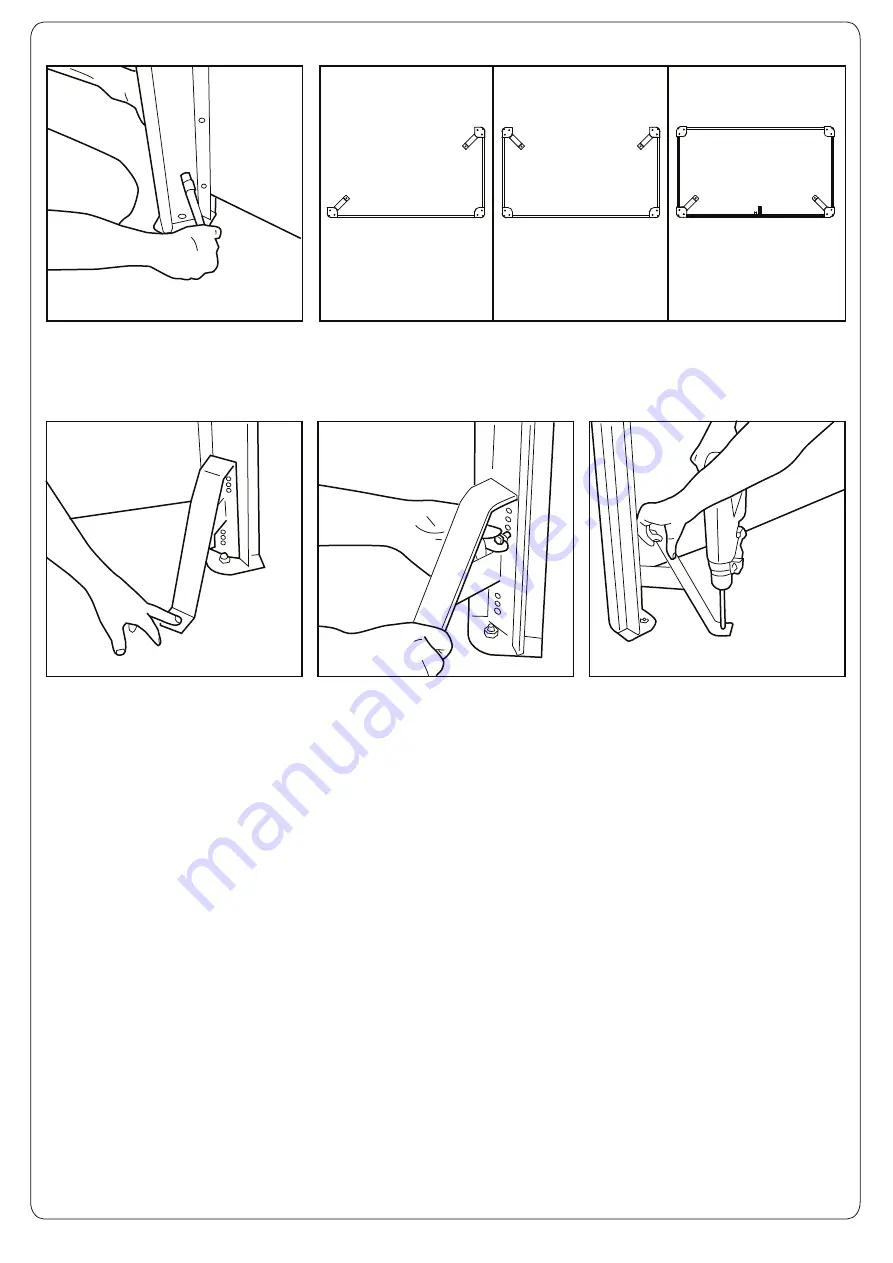
Using  a 13mm spanner/socket unscrew the two bolts with washers at the bottom of the outermost 

extrusions and remove. (see diagrams above showing location of support legs for all screen types) If the 

spigot legs have been adjusted (Step 1) the panels will need to remain lifted in position so that the support 

legs go into the correct holes. (may require two people.)     

Place the support leg (B) up 

against the inside of the extrusion 

so that the leg protrudes outwards 

and stands on the ground. If the 

spigot legs have been adjusted 

there are several pre-drilled holes 

in the support leg to 

accommodate this adjustment.

Replace the bolts and washers 

into the new holes through the 

support leg, extrusion and into 

the spigot leg. Tighten with 

13mm spanner/socket.    

Concrete fix the support legs into 

the ground as per Fig 10, 11 and 

12 (Step 2). 

Step 3: Attaching and Ground Fixing Compulsory Support Legs


13

14

15

16

P. 3

Two Sided

Three Sided

Four Sided c/w Door

Summary of Contents for Visage 770

Page 1: ...th the installation Please also refer to the Manual Handling Operations Regulations 1992 during the handling of the product and materials used for installation Total weight of the screens are Two Sided 770 40kg Three Sided 770 53kg Four Sided 770 80kg Two Sided 1280 46kg Three Sided 1280 65kg Four Sided 1280 92kg NOTE To allow the wheeled bin to sit inside the screen in the correct position it is ...

Page 2: ... a 10mm masonry drill bit drill through the hole in the spigot leg down into the concrete approximately 150mm deep Tighten bolt using 17mm spanner Repeat Figs 10 12 to ground fix the other extrusions P 2 TOOLS REQUIRED 13mm Spanner x1 17mm Spanner x2 Hand Drill with Pozi Drill Bit x1 10mm x 150mm Masonry Drill Bit x1 Hammer x1 6mm Allen Key x1 The fixing bolts A MUST appear as above with the nut a...

Page 3: ...support leg B up against the inside of the extrusion so that the leg protrudes outwards and stands on the ground If the spigot legs have been adjusted there are several pre drilled holes in the support leg to accommodate this adjustment Replace the bolts and washers into the new holes through the support leg extrusion and into the spigot leg Tighten with 13mm spanner socket Concrete fix the suppor...

Page 4: ...of Door Wheel If Required P 4 Step 4 Adjustment of Door Wheel on Four Sided Screen c w Door If Required 17 18 If the door is not level as seen above the door wheel can be adjusted Using 17mm spanner loosen nyloc nut on right hand side of wheel Using 17mm spanner and 6mm allen key loosen nut on left side of the wheel to free the axle from the wheel support bar 19 Using 17mm spanner hold the nut clo...

Page 5: ... Preston New Road BLACKPOOL Lancashire FY4 4UL Tel 01253 600410 Fax 01253 792558 E mail sales glasdon uk co uk Web www glasdon com TM P 5 26 27 28 Replace the wheel support bar over the bolts using the alternative holes to make the adjustment of the door height Making sure that the wheel support bar is 90 degrees to the door replace the washer and first nut onto the bolt and tighten do NOT overtig...

Reviews: