


AND MODUS ARE TRADEMARKS OF GLASDON GROUP AND ITS SUBSIDIARIES IN
THE U.K. AND OTHER COUNTRIES.
Replacement components are available direct from GLASDON.
GLASDON cannot be held responsible for claims arising from incorrect installation, unauthorised modifications or misuse of
the product.
Issue 2
December 2011
C000/0404
© Copyright 2011
Glasdon U.K. Ltd reserves the right to alter specifications without prior notice.
Preston New Road
BLACKPOOL
Lancashire FY4 4UL
Tel: 01253 600410
Fax: 01253 792558
E-mail: sales@glasdon-uk.co.uk
Web: www.glasdon.com
TM
P. 5
26
27
28
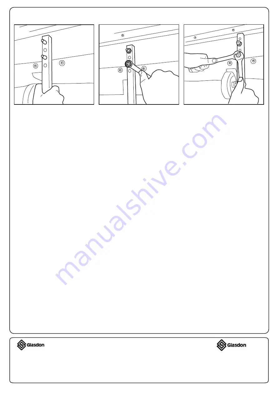
Replace the wheel support bar
over the bolts using the
alternative holes to make the
adjustment of the door height.
Making sure that the wheel
support bar is 90 degrees to the
door, replace the washer and first
nut onto the bolt and tighten (do
NOT overtighten).
Holding the nut with the 17mm
spanner, place the second nut
over the bolt and tighten securely
with a second spanner. Repeat
figs 27 and 28 using other fixings.
Step 5: Further Adjustment of Door Wheel (continued)


