21
GB
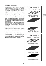
BUILT-IN INSTALLATION
with the tub rim flush with the floor. In this case, it is necessary
to create a supporting base under the bottom of the tub (concrete, steel H-beams).
WARNING:
It is also necessary to make arrangements for draining, in case of stagnant water,
the position of the drain pit depends on the type of installation.
Water under the spa for long periods of time may cause the wood to deteriorate.
It is also necessary to ensure the accessibility of the pipes and of all the electromechanical
organs unuder the tub, for instance by creating a passage around the external perimeter of the
tub. This passage must be wide enough (min. 80 cm) to house all the electrical and hydraulic
connections and to allow possible future maintenance operations; it can be closed by removable
mats, resting on suitable supports. To prevent condensation from forming in the pit, provide a
ventilation system ensuring an air passage of at least 200 mm diameter. The system must be
designed so that water cannot enter the pit.
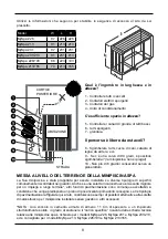
DELIVERY ACCESS
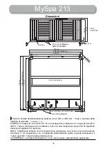
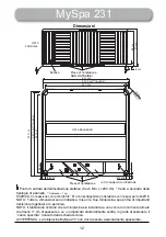
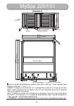
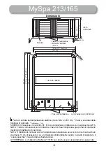
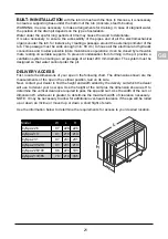
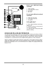
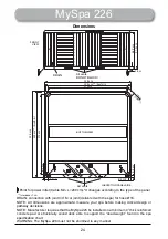
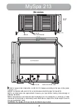
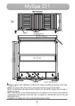
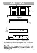
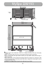
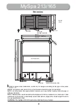
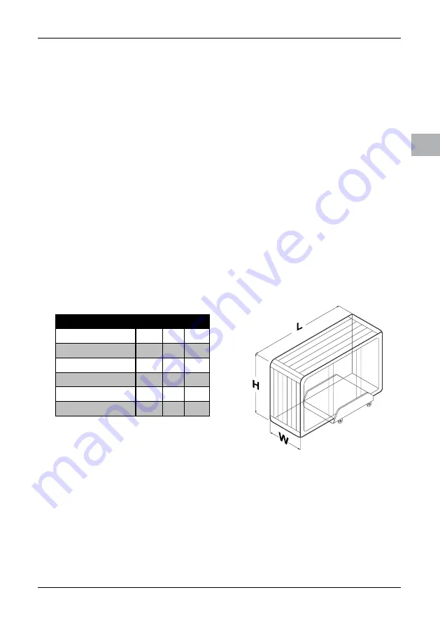
First, locate the dimensions of your spa on the following chart. The dimensions shown are the
measurements of the spa in the vertical position, laid on its side.
Next, contact your dealer to find the height and width added by the delivery cart which the dealer
will use to deliver your new spa. Use the height of the cart plus the dimension shown as H to
determine the vertical clearance required to pass the spa and cart. Use the width of the cart, or
dimension W, whichever is greater, to determine the maximum width of clearance necessary.
NOTE: It may be necessary to allow for additional over-head clearance if the spa will be rolled
up or down an incline or moved up or down a short flight of stairs.
Use the information below to determine the requirements for access to your desired location.
Model
W
L
H
MySpa 226
97
226 226
MySpa 213
91
213 213
MySpa 231
97
231 231
MySpa 231/213
91
231 213
MySpa 226/193
86
223 193
MySpa 213/165
74
213 165

