background image

Glastender, Inc.  •  5400 North Michigan Road  •  Saginaw, MI  •  48604-9780  

800.748.0423  •  989.752.4275  •  Fax 800.838.0888 / 989.752.4444  •  www.glastender.com

2

1.   electrIcal hOOKuP


•  Unit is supplied with a 20-amp line cord on the left rear  

  of the unit.


•  The main supply cord comes off the control box, located  

  on the pump deck.  The refrigeration power cord plugs        

  into the back of the control box, also located on the pump  

  deck.

2.   refrIgeratIOn start-uP


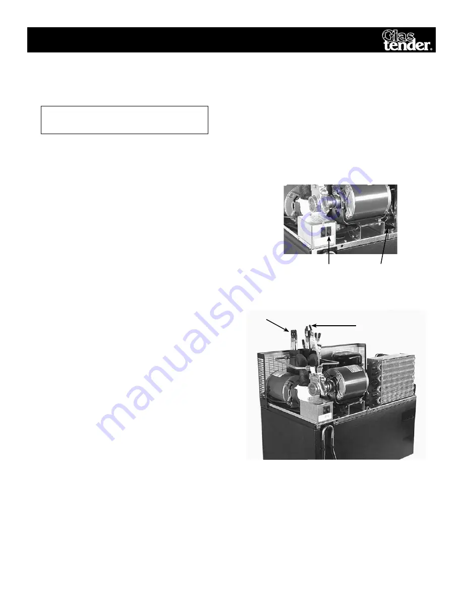
•  Remove top cover.  Locate the black plastic water bath  

  fill-plug and remove it. (see fig.3)


•  Fill the unit with clean water until water begins to come  

  out of the overflow tube. 


•  Plug in main power cord and the condenser fan and         

  compressor should start.  (see fig. 3)  If not,  refer to          

  “TROUBLESHOOTING PROCEDURES”. 


NOTE: A small amount of water will flow out of the over 

  flow tube until the ice is fully formed. 

3.   cOnnectIOn Of Water suPPly


•  Glastender, Inc. recommends that a 1/2” water line with        

  shut-off valve be installed within 10-ft. (3 M.) of the unit.            

  Incoming water pressure is not to be less that 20 P.S.I.


NOTE: If water pressure exceeds 60 P.S.I. or severely fluc-

tuates, a water pressure regulator is required ahead of the 

brass pump to avoid flooding the Carbonator. This regulator 

is not supplied as standard equipment


•  Before connecting water supply, drain approximately          

  two gallons of water from supply to flush out foreign             

  matter.  


•  It is recommended that a water filtering systems be        

  installed to reduce “off” tastes and odors. Use a system  

  that can filter out dirt particles 1 micron and larger.            

  Also amoebic and giardial cysts, asbestos fibers and           

  other similar contaminants.


•  Connect water supply to the 3/8” barb of the fitting of        

  the water-in tube.  (see fig. 4, Labeled Water Supply) 


•  Secure with proper sized “O” clamps.

4.   cOnnectIOn Of “PrODuct Out” lInes


•  Install the insulated bundled tubes on the 3/8” barb fittings.

i

nstaLLation

fig. 3

Control Box Switches

Filling the 

Water Bath 

fig. 4

   Connection of Water in Line


5. cOnnectIOn Of “PrODuct In” lInes


•  Install the 1/4” I.D. braided tubing from the syrup        

  supply location to the 1/4” male barb connections on  

  the unit.  Use tie wraps to neatly bundle supply lines.


•  Secure lines to product coils with “O” clamps.

Water-in Tube

Syrup and Soda Lines


•  Connect syrup out lines (3/8” male barb) to a color-      

  coded conduit.  (Note which numbered line goes to  

  which colored tube.) (see fig. 4) 


•  Secure connections with proper sized “O” clamps.


•  Connect the recirculating soda line (3/8” tubing) to            

  the barbed fitting coming from the insulated pump.          

  (see fig. 4)  Labeled “Soda Return”. 


•  Connect the other 3/8” line to the barbed fitting on the            

  soda coil.  Labeled “Soda Out”.  

nOte: thIs unIt reQuIres 20 

aMP cIrcuIt PrOtectIOn

Summary of Contents for LC84

Page 1: ...ichigan Road Saginaw MI 48604 9780 800 748 0423 989 752 4275 Fax 800 838 0888 989 752 4444 www glastender com Operation Manual and Parts Directory LC84 Conquest Post Mix Remote Soda Line Chiller 2006...

Page 2: ......

Page 3: ...Cleaning Hints 4 Water Bath Cleaning and Maintenance 4 Sanitizing Water Circuits 4 Sanitizing Syrup Circuits 4 Preventative Maintenance Schedule 5 Trouble shooting procedures Poor Carbonation 6 Bad T...

Page 4: ...ional 6 legs must be installed to the cabinet bottom If unit is installed on a countertop or shelf a the cabinet must be sealed to the countertop or shelf with an NSF listed silicon RTV applied around...

Page 5: ...standard equipment Before connecting water supply drain approximately two gallons of water from supply to flush out foreign matter It is recommended that a water filtering systems be installed to red...

Page 6: ...reely without spurting Adjust the syrup regulator to 50 P S I Adjust diet syrup regulator if used to 12 P S I Check all connections for leaks Insulate and tape all exposed refrigerated conduit lines A...

Page 7: ...nd pump deck Clean coils and inside of tank with soap or detergent and rinse with water Replace motor and pump deck Replace refrigeration deck Plug cord from refrigeration deck back into control box R...

Page 8: ...ice Weekly Dispensing Follow Standard Brixing Tower Brix Instructions Check Weekly Remote Cooler Wash With Mild Detergent And Wipe Dry Weekly System Review Pressure Gauges Pressures For Proper Setting...

Page 9: ...itch With switch in ON fully opened Incoming water supply to unit should be 3 8 I D minimums Be sure pump and pump motor are properly aligned and the clamp is tight Broken vanes in pump requiring pump...

Page 10: ...inks per minute Pull Down 6 9 hours operational Maximum Distance to Dispensers 150 ft 46 m Carbonator Integral cold carbonator Carbonator Pump 100 gph 378 lph Carbonator Motor 1 3 HP 25 kW Circulating...

Page 11: ...for ventilation and servicing Top front sides are one piece and are removable for servicing the compressor 1 625 Air Intake On Off Switch Compressor Area Under cover Exhaust Exhaust Exhaust Exhaust E...

Page 12: ...Road Saginaw MI 48604 9780 800 748 0423 989 752 4275 Fax 800 838 0888 989 752 4444 www glastender com Typical Installation Diagrams Typical Installation Using bag in box syrup system Typical Installat...

Page 13: ...hs from date of factory shipment whichever occurs sooner Glastender Inc will replace any part or assembly found defective under normal use and service Field replacement parts include a warranty of 90...

Page 14: ...5400 North Michigan Road Saginaw MI 48604 9780 800 748 0423 989 752 4275 Fax 800 838 0888 989 752 4444 www glastender com 11 LC84 Compressor and Related Parts 1 2 3 5 4 8 6 7 9 10 11 13 14 15 16 17 1...

Page 15: ...tion pump white set of 2 pieces 9 00 10 09000261 GT 031404 104 exterior power cord 20 00 11 09000412 GT 037112 Carbonator tank 115V 415 00 12 09000479 GT 034114 Relay compressor 20 00 09000480 GT 0312...

Page 16: ......

Reviews: