Page 25
MCB 1
6A
N
L
N
E
E
SL-
W
SL
-B
SL
-R
L1
L2
L3
N
N
N
SL
-F
SL
-H
E
E
240 V
AC ~
ROOM ST
AT
CONNECTIONS
240 V
AC ~
SUPPL
Y T
O
BOILER
N
3
2
4
1
L
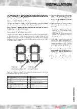
On a ‘No Clock Option’ an external 2
channel controller must be supplied
separately and connected as above.
(Factory Fitted Links between
L1- SL_H - SL_W will need to be removed)
Timed Outputs
HW O
ff
CH O
ff
HW On
CH On
On
On
Off
Off
Clock
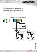
INSTALLER ELECTRICAL
CONNECTIONS
2 x 4 Core & Earth
1.0 mm
2
2 Core & Earth
1.0 mm
2
Feed Into
Appliance
Feed From
Appliance
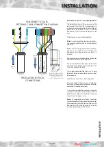
BOILERMATE ‘A’ CLASS
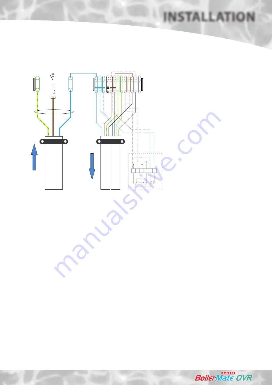
EXTERNAL CABLE CONNECTION DIAGRAM
G/Y
G/Y
Bl
Bl
Br
Br
Blk Blk
INST
ALL
ATION
INSTALLATION
Electrical Connection - Standard Appliance
The BoilerMate A-Class OVR is pre-wired to DIN
rail terminals from the A.C.B. and plumbers are
well able to complete the electrical installation
provided they adhere strictly to the IEE
Requirements for Electrical Installations BS
7671.
All the terminals are suitably labelled.
Note: Do not attempt the electrical work unless
you are competent to carry it out to the above
standards.
Before commencing check that the power
source is in accordance with the Site
Requirements section and ensure that it is
isolated.
Run the external wiring through the service slot
provided in the base of the appliance.
The twin and earth 2 core input cable from the
isolator to the appliance must not be less than
1mm
2
PVC grade to BS 6500.
This supply cable must be fed via a 13 amp
fused at 5 amps, no more than 2 metres from
the appliance.
Make the connections as shown opposite.
Clamp the cables in the clamps provided below
the terminal connections and ensure all cables
are routed to avoid hot surfaces.
Two installer supplied flex cables are required
to connect external room thermostat and
boiler. These cables must each be 4 core and
at least 1mm
2
or above in size.
Note: The appliance controller is polarity
sensitive therefore if the live and neutral cables
are connected incorrectly the red light on the
front panel will flash rapidly and can not be
reset by operating the push button.
Summary of Contents for BMAS 150 OVR
Page 38: ...Page 38 APPENDIX APPENDIX B ...
Page 40: ...Page 40 APPENDIX D NOTES ...
Page 41: ...Page 41 NOTES ...


