Page 22
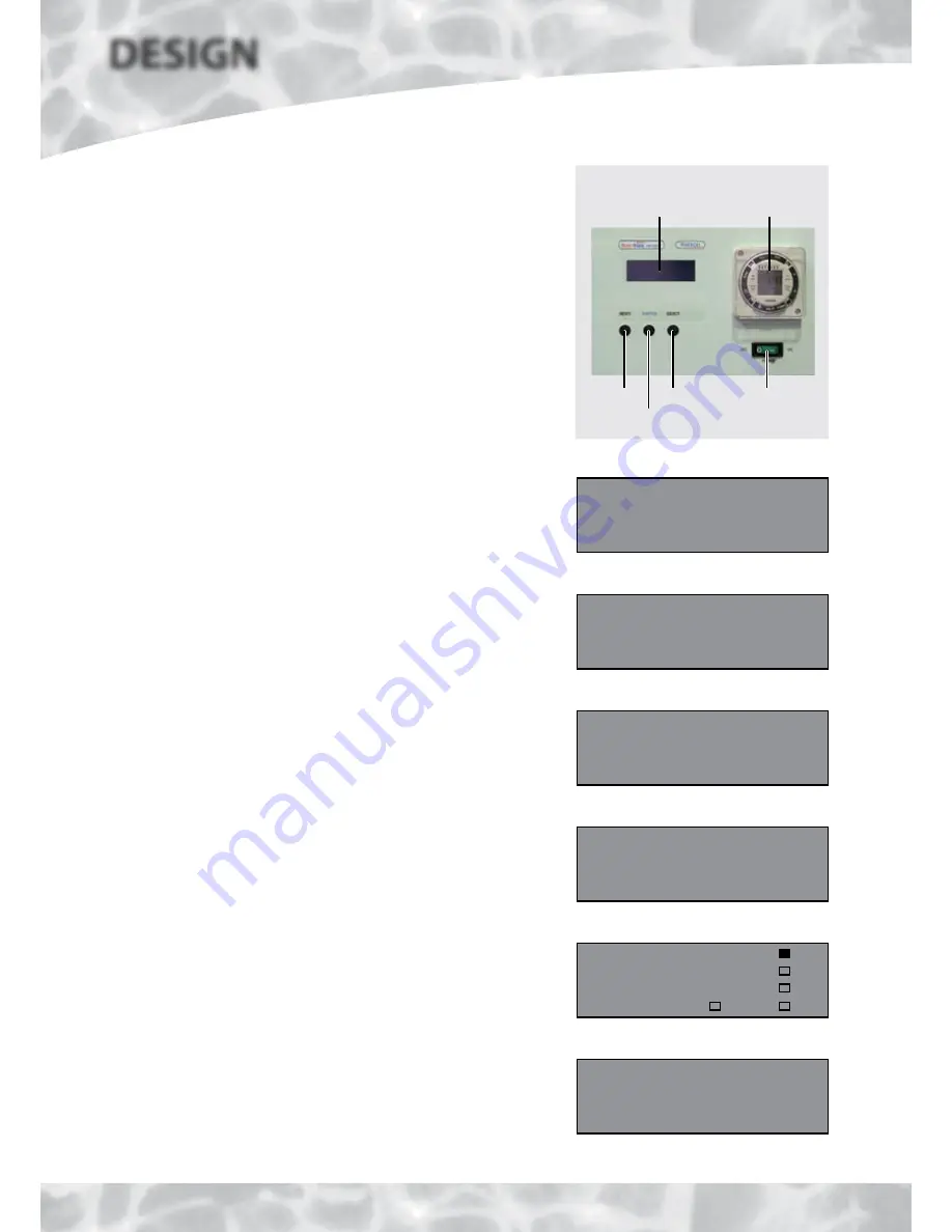
Front Panel User Controls
The front panel user controls are shown in the picture opposite and their functions
are described below.
Different windows can be accessed in the visual display panel on the front of the
appliance to indicate various temperatures and fault conditions.
2 Channel Clock
A 2 channel Grasslin clock is provided to allow separate control of the hot water and
heating requirements in accordance with the latest Building Regulations. Details of
how to set the clock are provided on the User label and in the User Instructions.
Channel 1 controls the operating times for the domestic hot water heating circuit.
This should normally be set to constant to allow the hot water to be available 24
hours a day.
Channel 2 controls the operating times for the zone 1 central heating circuit and
should be set to suit the householders lifestyle.
Note
: Electrical connections are provided on the terminal strip for a room thermostat.
With the two larger models, separate time and temperature controls such as a remote
programmable room thermostat will be required for the zone 2 central heating circuit.
Electrical connections are also provided for this on the terminal strip.
Normal Operating Display Window
In normal automatic heat pump operation the display will be as shown opposite.
Switch Operating Display Window
If a fault occurs with the heat pump, the ‘Switch’ emergency electric back-up system
can be selected by pressing and holding the ’Switch’ button below the display for at
least 5 seconds. The ‘Normal’ will change to ‘Switch’ and will flash.
Once the problem has been resolved, the appliance can be returned to normal
operation by pressing the ‘Switch’ button for at least 5 seconds.
Fault Condition Display Window
If a fault occurs with the BoilerMate A-Class HP-DEM appliance the window will
automatically display the fault condition. The window will flash alternately between
the two displays shown opposite.
The first window shows the fault reference code.
The second window shows a description of the actual fault condition.
Control/Status Display Window
By pressing the select button once when the window is in the normal operating mode,
the current temperatures and the status of the sensors/pumps can be seen as shown
typically opposite - also see Table 1.3 on page 12.
By pressing the select button twice, the set point values that are being used can be
seen as shown opposite.
Control Circuit Power Switch
This switch only controls the supply to the appliance control circuit. For service
the appliance must be isolated at the appropriate 2-pole isolator fitted adjacent
to the appliance.
Normal operating display
Boilermate-HP-DEM
Mode: Normal
Switch operating display
Boilermate-HP-DEM
Mode: Switch
Fault condition display
Boilermate-HP-DEM
Model: Fault 10
Fault condition display
Boilermate-HP-DEM
Sensor Fault
S1
S2
S3
S4
54
54
57
35
S5
S6
S7
CH-IH
38
48
14
P1
P2
P3
HW-IH
Control/sensor status display - current
Control/status display - set points
DESIGN
SY
STEM DET
AILS
HP
ST
1F
1R
3
8
58
56
2F
2R
TD
DE
45
35
3
60
H1
H2
HL
HW
50HBY
45
35
60WBY
Reset Select
Control
Circuit Switch
2 Channel
Clock
Visual Display
Window
Switch


