Page 11
DESIGN
SYSTEM DETAILS
Water
meter
Heat
meter
District
flow
Cold
water
District
return
Programmer
F&E
Cistern
DHW
Controller
DHW
Pump
Room
thermostat
DHW
24
Plate
PHE
Cylinder
thermostat
Back
up
immersion
heater
Diverter
Valve
(not
mid
position)
Cold
water
to
dwelling
DHW
to
dwelling
CH
flow
to
dwelling
CH
return
from
dwelling
BMS
Boilermate stainless
for
District
Heating
Coil
flow
connection
Coil
return
connection
Air
valve
Zone
valve
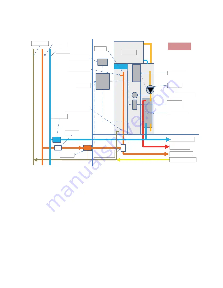
The above diagram shows the BoilerMate CP installed to a system where the pumped
supply is adequate to overcome the pressure loss of the BoilerMate CP heat exchanger
coil, the pressure loss over the central heating system components and all other
components fi tted to it. In addition, all the components fi tted are able to withstand
the pressure in the district system.
In the above diagram, the cold water supply to the feed and expansion cistern is not
shown, and neither is the overfl ow pipe which may by required if the ball valve is fi tted
to the F & E cistern. See page 9 for further details. Potentially a temporary fi lling loop
complying with the water regulations can be installed.
Summary of Contents for BoilerMate CP 120
Page 26: ...Page 26 APPENDIX APPENDIX B ...


