Page 40
SERVICING AND MAINTENANCE
FAULT FINDING
Test Equipment
The initial assumption in this procedure is that the plumbing and water supply is
working effectively. If in doubt please confirm and refer to the end of this section for
advice on specific components.
A multi meter, a weir gauge and a thermometer will be required to confirm that all
the components are working effectively.
The PWM controller PCB manufacturer suggests “Fluke 87 TRUE RMS Multi meter” as
a suitable product. This will be able to measure;
- the frequency output form the Board to the pump
- the Duty cycle % output from the Board to the pump
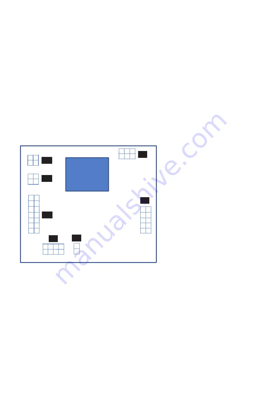
Connection numbering
For reference the connections to the PCB are numbered below for
Logical sequence;
- check electrical connections fault finding section on page 23 first to ensure your
own safety. This section will potentially identify any short circuited components
and/or wiring faults that need to be rectified before continuing to work on the
appliance.
- check that the correct information is being supplied to the board. This section will
identify if any sensors are faulty or out of tolerance. These will need to be replaced
before continuing
- check that the overheat link is present
- check that the outputs to the board are being generated. If at this stage the board
does not provide the correct outputs then potentially the board should be replaced
- check the pump electrical circuit
1
2
3
4
5
6
7
8
9
10
11
12
13
14
1
2
3
4
1
2
3
4
1
2
3
4
5
6
7
8
1
2
1
2
3
4
5
6
7
8
9
1
10
2 3
4 5 6
J18
J20
J19
J3
J7
J8
J1
Summary of Contents for BOILERMATE OV PP
Page 47: ...Page 47 APPENDIX APPENDIX B ...


