Page 18
3.4 ELECTRICITY SUPPLY
AND WIRING DIAGRAMS
The mCHP_BoilerMate
A-CLASS
is fitted with a
electric backup heater rated at 6kW as standard.
Therefore the single mains electricity supply
to the appliance must be rated at 32A at 230V
ac and connected to the appliance through
a 2-pole local isolator. All fuses must be ASTA
approved to BS 1362. This supply is internally
split and fused for the control and power
circuits. This appliance MUST BE EARTHED.
The BoilerMate only supplies the control
signal power to the mCHP unit. Therefore the
mCHP unit must be connected to the mains
supply via its dedicated 2-pole isolator as
per manufacturer’s instructions.
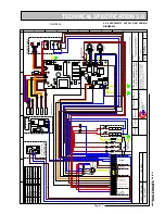
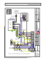
The internal wiring diagram is shown in figure
3.6 and typical external wiring arrangement is
shown schematically in figure 5.2.
3.5 APPLIANCE
CONTROLLER
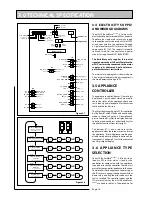
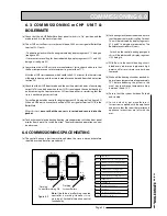
The appliance controller (figure 3.7) has a 2 digit
display and 2 push buttons which are used to
check the status of the appliance, check and
set its identity and interrogate it for the current
faults and the fault history.
The 2 digit display on the main PCB is controlled
by 2 buttons B1 and B2 The flow chart of display
modes is shown in figure 3.8. Generally, each
press of button B1 cycles the display from top
to bottom and each press of button B2 cycles
the display functions from left to right.
The buttons B1 is also used to reset the
appliance i.e. clear the lockout errors and reset
the appliance. (Note: Appliance resetting can
also be carried out using the push button on the
front panel). See figure 6.2 for further details of
the 2 digit digital display.
3.6 APPLIANCE TYPE
SELECTION
The mCP BoilerMate
A-CLASS
is fitted with an
identity (iD) resistor which is read by the
controller for comparison with the appliance
type (code) set on the controller. The two must
match for the controller/appliance to function.
Therefore if either the appliance code setting or
the iD resistor is wrong, the appliance will shut
down safely and flag the error code until the
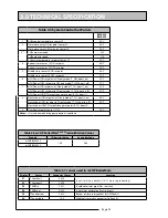
fault is rectified. The controller codes and the
iD resistor values for the mCHP-BoilerMate
A-
CLASS
are listed in table 3.6. The procedure for
3.0 TECHNICAL SPECIFICATION
Tank_middle
T_overh_2
T_dhw_in
ID_resistor
T_overh_1
Tank_bot
T_dhw_out
ID_resistor
ID_resistor
Ext_led_k
Ext_se_1
PC Connector
Reset
button
Enter
button
Main processor
FLIP jumper
J9
J31
J30
SEND_TO_GAS
VSS
GASV_IN
220_0
WD_RECEIVE
VSS
SAFETY
220_1
J29
DIV_OUT_2
220-0
DIV_OUT_1
220_0
EL_HEAT_OUT
BOIL_HEAT_DEM
OVERHEAT
220_0
BOIL_HEAT_DEM
CH_P_MOD
CH_P_L
CH_P_L
CH_P_PE
BOIL_P_PE
BOILER_P_MOD
BOIL_P_L
BOIL_P_N
DHW_P_PE
DHW_P_MOD
DHW_P_L
DHW_P_N
220_1
220_PE
220_0
220_PE
220_1
220_0
CH_ON_IN
220_0
220_1
SWL_IN
DHW_ON_IN
220_INPUT
J3
J33
J32
J34
J28
J5
2 digit display
B1
B2
.ORMALSTANDBYSTATE
)NDICATESYSTEMSTATUS
3EESECTION
3ENSORTEMPERATUREREADING
3EESECTION
3ETPOINTREADING
3EESECTION
&AULTCODE)NDICATION
,OCKOUTS
3EESECTION
3
3
3
3
3
3
3
3
#
#
#
#&
C
C
C
C&
!
!
!
!
&AULTCODEINDICATION
"LOCKOUTS
3EESECTION
!PPLIANCE4YPE
3EESECTIONS
0RESS"
0RESS"
0RESS"
0RESS"
0RESS"
0RESS"
0RESS"
0RESS"
0RESS"
0RESS"
0RESS"
0RESS"
0RESS"
0RESS"
0RESS"
0RESS"
0RESS"
0RESS"
0RESS"
0RESS"
0RESS"
0RESS"
0RESS"
0RESS"
0RESS"
"
"
Figure 3.7
Figure 3.8
Summary of Contents for mCHP BMA 225
Page 44: ......


