Page 13 of 16
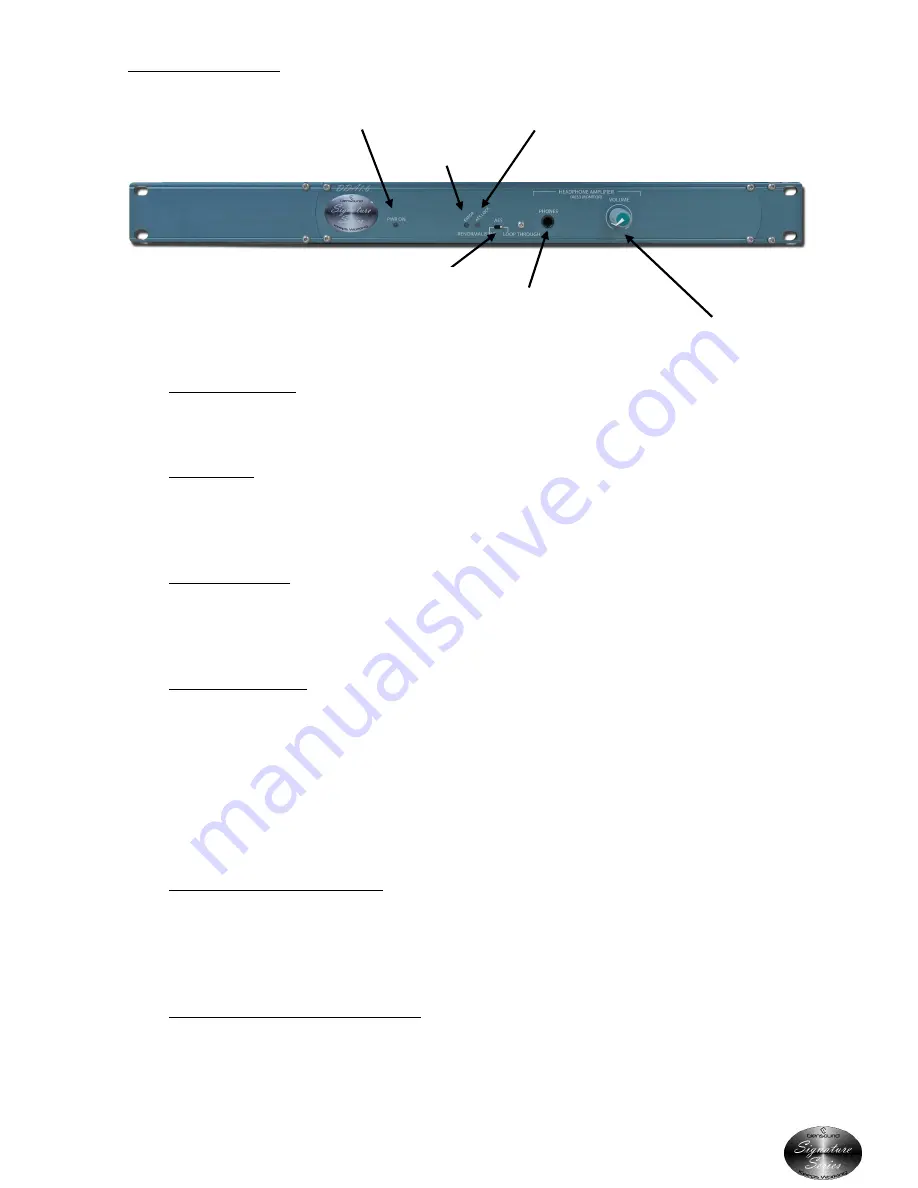
USER CONTROLS
1.
Power On LED
The front panel bright blue LED shows that the unit is powered on and functioning correctly.
2.
Error LED
The error LED is fed from the output of the AES3 receiver and will be illuminated whenever
the receiver is not receiving a valid AES3 signal.
3.
AES Lock LED
This LED is connected to the output of the AES3 receiver. If illuminated it indicates that the
receiver has detected a valid AES3 signal and is correctly locked onto it.
4.
Selector Switch
When in the ‘Renormalising’ position the AES3 outputs of the unit will be cleaned up and
‘renormalised’ so as they have clear sharp clock edges and mirror the original AES3 signal. It
takes 1 sample to do this so the output will be sample behind the input.
When in ‘Loop Through’ mode the AES3 outputs will be identical to the input, so if the input
signal has been degraded by a long cable run or noise, then the output signal will reflect this
identically.
5.
Headphone Jack Socket
This is a standard 6.35mm (1/4”) stereo headphone jack socket. The audio output is taken
from the AES3 input and it can be used as a monitor point to ascertain audibly the quality of
the incoming circuit.
6.
Headphone Volume Control
Turning this control clockwise will increase the audio output level of the headphone
amplifier.
2.
POWER ON LED
3.
ERROR LED
1.
AES LOCK
5.
SELECTOR SWITCH
4.
HEADPHONE JACK SKT
6.
HEADPHONE
VOLUME CONTROL


