background image

Glentek Inc.  208 Standard Street, El Segundo, California 90245, U.S.A.  (310)  322-3026 

18 

GA369 MANUAL 

CHAPTER 6: START UP AND ADJUSTMENT PROCEDURE 

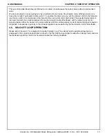
1.   It is possible, at this time, that the Digital Loop is reverse phased. An example of this would be if a positive 
voltage from the velocity DAC required the motor to turn CW, however, it turned CCW instead causing the encoder 
feedback signal to count up instead of down. This would cause a run away condition. 

If you are out of phase as described, be sure power is OFF and reverse the motor leads at the amplifier and also the 
tachometer leads. This will cause the motor to rotate in the opposite direction as it did before, properly phasing the 
Digital Loop. 

2.   Now with the Digital Loop operating, turn the Loop Gain potentiometer, R1B, fully CW and command a small 
move. Slowly increase or decrease the Signal Gain potentiometer, R12 or R13, of the amplifier until the servo is 
operating as required. It should be noted here that too much Signal Gain at this point could cause instability 
(oscillation). 

Do not 

stay in this oscillating condition long as it may result in system mechanical or electrical damage. 

Be sure when all signal adjustments are made that the balance is rechecked and adjusted for zero rotation for zero 
signal input. 

3.   It should be noted here that the GA369 are designed to operate with many different systems and if after reading 
this manual you have further questions, do not hesitate to call a Glentek applications engineer. 

ENGINEERING NOTE: 

After all systems are aligned and functioning it is good practice to remove power from the amplifier and, using a 
digital ohm-meter, measure the impedance value of the following potentiometer wiper settings with respect to signal 
ground. These values may be useful for the next machine you align or for maintenance of this system at a later date. 
Make these measurements on each amplifier on a multiaxis baseplate. 

Record resistance measurements: 


AMP 1 

AMP 2 

AMP 3 

AMP 4 

AMP 5 

AMP 6   


Tach. potentiometer wiper to signal 
ground. (ohms): 


Signal potentiometer wiper to signal 
ground. (ohms): 


Comp. potentiometer wiper to signal-
ground. (ohms): 


Current limit potentiometer wiper to 
signal ground (ohms): 


Signal voltage 
Tachometer voltage 

——— 

——— 

——— 

——— 

——— 

——— 


               Date Taken:    ____  ____  ____               Note any changes to compensation components, etc.: 

Summary of Contents for GA369

Page 1: ...OPERATION SERVICE MANUAL Model GA369 Pulse Width Modulated Servo Amplifier...

Page 2: ...D Bi0 B13 8 2 4 6 TYPICAL FACTORY SETTINGS 8 CHAPTER THREE PERSONALITY PREAMP CARD 3 1 INTRODUCTION TO THE PERSONALITY PREAMP CARD GA369 3 9 3 1 1 VELOCITY MODE PERSONALITY PREAMP CARD 9 3 1 2 CURRENT...

Page 3: ...7 3 FACTORY REPAIR 20 7 4 WARRANTY 20 APPENDIX A FAULT TRACING CHARTS FAULT CHART 1 Motor does not turn in either direction 22 FAULT CHART 2 Motor only turns in one direction 23 FAULT CHART 3 Motor w...

Page 4: ...GA369 We suggest that you take the time to read this manual from cover to cover before trying to work with a GA369 amplifier If you have any questions that you can not find the answer to in this manu...

Page 5: ...erent end of travel limit circuits with pull up resistors 4 7k to either 5VDC or 1 5VDC Refer to Appendix C drawing 369 1200 Type A Requires grounding of pin 8 or pin 9 to disable amplifier To impleme...

Page 6: ...excessive mechanical bind in the system or possibly driving into a hard mechanical stop Circuit operation is as follows When the motor current exceeds the value set at TP1 typically 3 0 VDC scale fac...

Page 7: ...to common Total Inhibit Type A Activated by a 3ma contact closure to common Gnd to reset Activated by a 3ma contact closure to common Fault Monitor 4 7k ohm pull up to 5VDC or 15VDC will sink 50 ma 2...

Page 8: ...feedback However the high gain input summing amplifier can be bypassed providing an input directly to the current loop amplifier Current Mode option If the Current Mode CM option is specified the Vel...

Page 9: ...ent command output 3 CURRENT SENSE Current sense input 4 LIMIT Limit output 5 LIMIT Limit output 6 15VDC 15VDC power 7 COMMON 15 VDC and signal common 8 COMMON 15 VDC and signal common 9 COMMON 15 VDC...

Page 10: ...tion 4 3 H TYPE OUTPUT BRIDGE CONFIGURATION The output configuration of the amplifier is a H TYPE bridge see fig 4 2 for schematic representation of output bridge with motor connected The advantage of...

Page 11: ...of how the current is provided from an H TYPE Pulse Width Modulated PWM bridge let s analyze the operation of the current loop 4 5 CURRENT LOOP OPERATION Please refer to figure 4 1 for a diagram of t...

Page 12: ...car current command signal The selected temperature is then summed with the actual temperature from a thermometer current feedback and the output current error signal activates either the heater or th...

Page 13: ...ire size must be sufficient to accommodate the maximum continuous current that will be run thru it Recommended wire sizes for the GA369 are as follows MOTOR ARMATURE 14 ga 0 105 VAC POWER INPUT from s...

Page 14: ...he preamp card see appendix C drawings 369 1200 and 369 1202 It is an isolated output signal that is proportional to motor current The scale factor is 1 VOLT 2 AMPS 5 4 6 AND LIMITS The and Limits are...

Page 15: ...Preamp card Refer to Appendix C drawings 369 1200 369 1202 6 3 VELOCITY LOOP PHASING For proper servo operation it is necessary for the amplifier to receive negative feedback from the tachometer If t...

Page 16: ...locity loop remains stable If the waveform is still under damped after adjusting the Compensation potentiometer for maximum bandwidth turn the Tachometer Gain potentiometer R21 2 turns CCW and then ag...

Page 17: ...ay in this oscillating condition long as it may result in system mechanical or electrical damage Be sure when all signal adjustments are made that the balance is rechecked and adjusted for zero rotati...

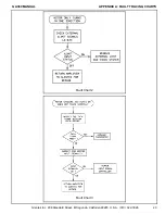
Page 18: ...he top of each chart Follow the line connections between blocks by your answers to the questions noted in the diamond shape blocks until the defective part is isolated The charts are to be used only a...

Page 19: ...ant of the original purchaser thereof proves defective in material or workmanship within one year from the date of shipment by us as determined by an inspection by us will be replaced free of charge F...

Page 20: ...Glentek Inc 208 Standard Street El Segundo California 90245 U S A 310 322 3026 21 GA369 MANUAL APPENDIX A FAULT TRACING CHARTS APPENDIX A FAULT TRACING CHARTS...

Page 21: ...Glentek Inc 208 Standard Street El Segundo California 90245 U S A 310 322 3026 22 GA369 MANUAL APPENDIX A FAULT TRACING CHARTS Fault Chart 1...

Page 22: ...Glentek Inc 208 Standard Street El Segundo California 90245 U S A 310 322 3026 23 GA369 MANUAL APPENDIX A FAULT TRACING CHARTS Fault Chart 2 Fault Chart 3...

Page 23: ...Glentek Inc 208 Standard Street El Segundo California 90245 U S A 310 322 3026 24 GA369 MANUAL APPENDIX A FAULT TRACING CHARTS Fault Chart 4...

Page 24: ...Glentek Inc 208 Standard Street El Segundo California 90245 U S A 310 322 3026 25 GA369 MANUAL APPENDIX A FAULT TRACING CHARTS Fault Chart 5...

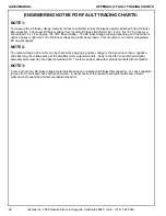
Page 25: ...t load The DC Buss voltage sag under heavy loads This of course is normal for unregulated DC power supplies NOTE 2 The output voltage to the motor can be checked by applying a positive voltage to the...

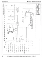
Page 26: ...Glentek Inc 208 Standard Street El Segundo California 90245 U S A 310 322 3026 27 GA369 MANUAL APPENDIX A AMPLIFIER DRAWINGS APPENDIX B AMPLIFIER DRAWINGS...

Page 27: ...Glentek Inc 208 Standard Street El Segundo California 90245 U S A 310 322 3026 28 GA369 MANUAL APPENDIX A AMPLIFIER DRAWINGS...

Page 28: ...Glentek Inc 208 Standard Street El Segundo California 90245 U S A 310 322 3026 29 GA369 MANUAL APPENDIX A AMPLIFIER DRAWINGS...

Page 29: ...Glentek Inc 208 Standard Street El Segundo California 90245 U S A 310 322 3026 30 GA369 MANUAL APPENDIX A AMPLIFIER DRAWINGS...

Page 30: ...Glentek Inc 208 Standard Street El Segundo California 90245 U S A 310 322 3026 31 GA369 MANUAL APPENDIX A AMPLIFIER DRAWINGS...

Page 31: ...Glentek Inc 208 Standard Street El Segundo California 90245 U S A 310 322 3026 32 GA369 MANUAL APPENDIX A AMPLIFIER DRAWINGS...

Page 32: ...Glentek Inc 208 Standard Street El Segundo California 90245 U S A 310 322 3026 33 GA369 MANUAL APPENDIX A AMPLIFIER DRAWINGS...

Page 33: ...Glentek Inc 208 Standard Street El Segundo California 90245 U S A 310 322 3026 34 GA369 MANUAL APPENDIX A AMPLIFIER DRAWINGS...

Page 34: ...Glentek Inc 208 Standard Street El Segundo California 90245 U S A 310 322 3026 35 GA369 MANUAL APPENDIX C PERSONALITY MODULE DRAWINGS APPENDIX C PERSONALITY MODULE DRAWINGS...

Page 35: ...Glentek Inc 208 Standard Street El Segundo California 90245 U S A 310 322 3026 36 GA369 MANUAL APPENDIX C PERSONALITY MODULE DRAWINGS...

Page 36: ...Glentek Inc 208 Standard Street El Segundo California 90245 U S A 310 322 3026 37 GA369 MANUAL APPENDIX C PERSONALITY MODULE DRAWINGS...

Page 37: ...Glentek Inc 208 Standard Street El Segundo California 90245 U S A 310 322 3026 38 GA369 MANUAL NOTES...

Page 38: ...near Brushless servo amplifiers to 3 5KW PWM Pulse Width Modulated Brushless servo amplifiers to 51KW Permanent Magnet DC Brush Type Servo Motors Continuous Torques to 335 in lb Peak Torques to 2100 i...

Reviews: