Glentek Inc. 208 Standard Street, El Segundo, California 90245, U.S.A. (310) 322-3026
26
GA369 MANUAL
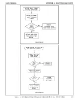
APPENDIX A: FAULT TRACING CHARTS
ENGINEERING NOTES FOR FAULT TRACING CHARTS:
NOTE 1:
To measure the DC Buss voltage, carefully connect a voltmeter across the bleeder resistor attached to the DC Buss
filter capacitor. The proper DC Buss voltage from the main DC Buss transformer by 1.4 (Ex: For 70 VAC input you
should read 70 x 1.4 or approx. 100 VDC Buss voltage). The DC Buss voltage will vary depending on if the motor is
under a heavy or light load. The DC Buss voltage sag under heavy loads. This of course is normal for unregulated
DC power supplies.
NOTE 2:
The output voltage to the motor can be checked by applying a positive voltage to the signal input, then a negative,
and observing the voltage swing at the amplifier motor output terminals. Keep in mind the Loop Gain and signal
potentiometers must be set at least somewhat CW. This test can be made with motor disconnected from amplifier.
NOTE 3:
A low, but not zero, DC Buss voltage could indicate an open or defective DC Buss filter capacitor. To check capacitor
remove from circuit and check with an ohmmeter. A visual check of the capacitor seal port could show a blown
pressure seal caused by a failed, overheated capacitor.


