Model No.
Input
Type
Watt
Output Range
+3.3V
+5V
+12V1
+12V2
-5V
-12V
+5Vsb
3107760
AC
AT
390W
N/A
40A
15A
N/A
0.3A
0.8A
N/A
3102060
AC
ATX
300W
28A
30A
15A
N/A
0.3A
0.8A
2A
3102050
AC
ATX
400W
28A
33A
20A
N/A
0.5A
1A
2A
3102030
AC
ATX
500W
27A
29A
18A
18A
0.3A
0.8A
2A
3107770
AC
ATX
300W
18A
25A
16A
N/A
0.5A
0.5A
2A
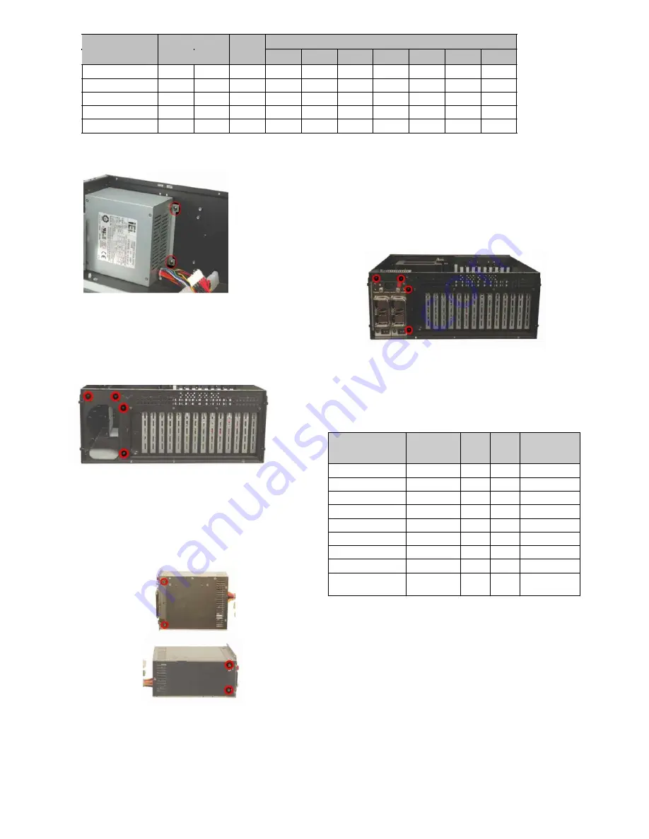
Table 2: Compatible Global American, Inc PSUs.
Step 4:
Install a redundant PSU at the rear of the chassis. Make
sure both the power socket and the PSU fans face the rear
of the chassis.
Step 5:
To secure the redundant PSU to the chassis, reinsert the
four previously removed PSU frame retention screws.
Step 0:
Figure 6: PSU Internal Retention Screws
The 1404150 chassis can also support a redundant PSU. To install
a redundant PSU, follow the steps outlined below:
Step 1:
Remove the PSU frame by removing the four retention
screws from the rear of the chassis.
Figure 9: Redundant PSU Retention Screws
STEP 4: BACKPLANE INSTALLATION
The Global American, Inc backplanes listed below are compatible with
the 1404150
chassis.
Model No.
SBC
Interface
PCI
ISA
PSU
Connector
Figure 7: PSU Frame Retention Screws
Step 2:
Attach two redundant PSU clamps to the PSU, one to the
top and the other one to the left side of the redundant
PSU.
Step 3:
Insert two retention screws for each clamp to secure the
clamps to the redundant PSU.
1101014
ISA
N/A
14
AT
1107740
PICMG 1.3
2
N/A
ATX
1107900
PICMG 1.3
4
N/A
ATX
1103460
PICMG 1.0
3+4
3+3
AT/ATX
1101070
PICMG 1.0
4
8
AT/ATX
1101129
PICMG 1.0
4
9
AT/ATX
1103764
PICMG 1.0
12
2
AT/ATX
1107643
PICMG 1.0
7
6
AT/ATX
1104120
PCIAGP
11
N/A
AT/ATX
Table 3: Compatible Backplane Modules
To install a backplane please follow the instructions below.
Step 1:
Mount the backplane onto the base of the chassis and find
out the corresponding retention screw holes in the base of
the chassis.
Step 2:
Insert nine copper pillars in the nine corresponding holes in
the base of the chassis.
Figure 8: Redundant PSU Clamp Retention Screws
1404150 QIG
Page 6


