the power connector and the IDE/SATA connector face the
rear of the bracket.
Step 4:
Align the 3.5” FDD retention screw holes with the retention
screw holes in the 3.5” drive bay. Make sure the front of the
FDD is aligned with the front of the drive bracket.
Step 5:
To secure the 3.5” FDD insert four retention screws.
Step 0:
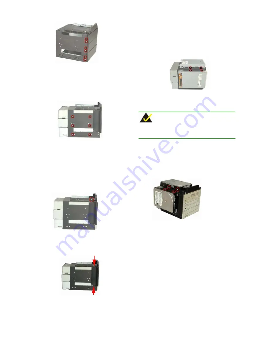
Figure 22: 5.25” Drive Bay Front Cover Retention Screws
Step 4:
Slide a 5.25” optical drive into the 5.25” drive bay making
sure
both
the
power
connector
and
the
IDE/SATA
connector face the rear of the chassis.
Step 5:
Insert four retention screws, two into each side of the
drive bay to secure the 5.25” optical drive.
Step 0:
Figure 26: FDD Retention Screws
To install a 3.5” HDD, follow the steps below.
NOTE:
When 3.5” HDDs are installed, the front covers of the 3.5” drive
bays do not need to be removed.
Figure 23: 5.25” Optical Drive Retention Screws
S
TEP
8.3: FDD/HDD I
NSTALLATION
To install a 3.5” FDD, follow the steps below.
Step 1:
Remove the drive bracket. To do this, please refer to
S
TEP
8.1: D
RIVE
B
RACKET
R
EMOVAL
.
Step 2:
Remove the 3.5” drive bay front cover by removing the
two retention screws, one from each side.
Step 1:
Mount a 3.5” HDD onto the 3.5” drive bay. Make sure both
the power socket and the IDE/SATA connectors face the
rear of the chassis.
Step 2:
Align the 3.5” HDD retention screw holes with the retention
screw holes in the 3.5” drive bay.
Step 3:
To secure the 3.5” HDD, insert four retention screws, two
into each side of the 3.5” HDD.
Step 0:
Figure 27: HDD Retention Screws
Figure 24: Top 3.5” Drive Bay Front Cover Retention
Screws
S
TEP
8.4: D
RIVE
B
RACKET
R
EINSTALLATION
After the disk drives have been properly installed into the drive brackets,
reinstall the drive brackets into the chassis. To reinstall the drive
brackets into the chassis please follow the steps below.
Step 1:
Place the main drive bracket into the chassis. Make sure the
front of the drives face out of the chassis, the power
connectors and IDE/SATA interface connectors all face the
rear of the chassis, and the two clips at the bottom of the
bracket slides into the bracket at the base of the chassis.
Figure 25: Left 3.5” Drive Bay Front Cover Retention Screws
Step 3:
Mount a 3.5” FDD onto the 3.5” drive bay. Make sure both
1404150 QIG
Page 9


