Step 3:
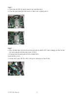
a. Verify that the CPU if properly mated to the orientation keys.
b. Close the upper plate, place the load lever back to the original position.
Step 4:
a. Place the Heat Sink with Fan Set onto the four holes around the CPU socket making sure that the four
screws are aligned with the holes on the 3301520.
b. Pressing down the metal pads on the four Stand-Offs. c.
Fasten the four screws.
d. Connect the 4-pins CPU fan cable to the power connector as shown below.
3301520 User s Manual
31
Summary of Contents for 3301520
Page 1: ...User s Manual 3301520...
Page 5: ...This Page is Left Blank Intentionally 3301520 User s Manual 4...
Page 6: ...Chapter 1 General Information 3301520 User s Manual 5 Chapter 1...
Page 11: ...1 4 Board Layout Figure 1 2 Overview of 3301520 3301520 User s Manual 10 Chapter 1...
Page 13: ...Chapter 2 Jumper Setting 3301520 User s Manual 12...


