3307800
Page 39
4.1 Peripheral Interface Connectors
Section 4.1.2 shows peripheral interface connector locations. Section 4.1.2 lists all the
peripheral interface connectors seen in Section 4.1.2.
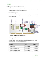
4.1.1 3307800 Layout
Figure 4-1
shows the on-board peripheral connectors, rear panel peripheral connectors
and on-board jumpers.
Figure 4-1: Connector and Jumper Locations
4.1.2 Peripheral Interface Connectors
Table 4-1
shows a list of the peripheral interface connectors on the 3307800. Detailed
descriptions of these connectors can be found below.
Connector
Type
Label
Audio connector
10-pin header
FPAUDIO1
Cooling fan connector, CPU
3-pin header
CPU_FAN1
Cooling fan connector, System 3-pin
header
CPU_SYS1
Summary of Contents for 3307800
Page 1: ...User s Manual Single Board Computer 3307800 Version 1 0 June 2007 ...
Page 14: ......
Page 15: ...Page xvi THIS PAGE IS INTENTIONALLY LEFT BLANK ...
Page 16: ...3307800 Page 1 1 Introduction Chapter 1 ...
Page 22: ...3307800 Page 7 2 Detailed Specifications Chapter 2 ...
Page 47: ...3307800 Page 32 3 Unpacking Chapter 3 ...
Page 52: ...3307800 Page 37 THIS PAGE IS INTENTIONALLY LEFT BLANK ...
Page 53: ...3307800 Page 38 4 Connector Pinouts Chapter 4 ...
Page 68: ...3307800 Page 53 Figure 4 9 Mini PCI Slot Location ...
Page 87: ...3307800 Page 72 5 Installation Chapter 5 ...
Page 114: ...3307800 Page 99 THIS PAGE IS INTENTIONALLY LEFT BLANK ...
Page 115: ...3307800 Page 100 ...
Page 116: ...3307800 Page 101 A DIO Interface Appendix B ...
Page 119: ...3307800 Page 104 THIS PAGE IS INTENTIONALLY LEFT BLANK ...
Page 120: ...3307800 Page 105 B Watchdog Timer Appendix C ...
Page 122: ...3307800 Page 107 ...
Page 124: ...3307800 Page 109 THIS PAGE IS INTENTIONALLY LEFT BLANK ...
Page 125: ...3307800 Page 110 C Address Mapping Appendix D ...
Page 128: ...3307800 Page 113 THIS PAGE IS INTENTIONALLY LEFT BLANK ...


