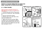
background image

(VII)Strongly recommend to

 establish and respect periodic maintenance schedule

, which will 

be determined by the frequency and length of your rides,your style of riding, as well as the 

terrain on which you most often ride.

(VIII)

Recommended torque requirements

 in newton meters for the following:

(A)  Front axle nuts.                          15-25NM

(B)  Back axle nuts.                          20-30NM

(C)  Handlebar clamp nut/bolt.          8-12NM

(D)  Handlebar stem expander bolt. 35-45NM

(E)  Seat pillar clamp nut/bolt.          18-22 NM          (K) Pedal.                               35-40NM                          

(F)  Brake cable anchor bolt.    1.5-4NM

(G)  Brake mounting bolt.          8-12NM

(H)  Seat clamp nuts.                18-22NM

(I)  Crank attachment systems. 40-60NM

(IX)

HOW TO CHOOSE SAFE SIZE OF THE BIKE 

Rider must be able to straddle bicycle with 

at least 1 inch (2.54cm) clearance above the  horizontal bar when standing.
(X)

Please check before riding

1. 

STEERING:

 Make certain that the stem is inserted into the head tube to at least

the minimum insertion line. Check the clamp nut and stem bolt to make sure they

are tightened securely. 

2. 

SEAT

: Check for tightness of seat clamp and seat post clamp and that the

minimum insertion line is inside the frame. See that the seat is at the proper

height for the intended rider.

Perform each check list below after all assembly instructions and any necessary

adjustments have been completed. Warning: Failure to perform these checks could

result in serious injury to yourself and others.

3.

GENERAL INSPECTION

: See that all reflectors have been properly installed.

Replace any missing or damaged reflectors. Check all fasteners and tighten if

necessary.

Summary of Contents for EVOLT

Page 1: ...Global Fitness and Leisure Pty Ltd 23 25 Maygar Blvd Broadmeadows VIC 3047 Australia Ph 1300 169 600...

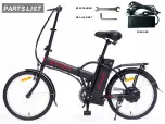
Page 2: ...PARTS LIST M15 SPANNER M6 ALLEN KEY CHARGER...

Page 3: ...ORE RIDING CHARGE BATTERY IMPORTANT TIPS ADVICE ASSEMBLY FOLDING INSTRUCTIONS CLEANING LUBRICATION WARRANTY TROUBLESHOOTING NOTES FOR USERS PREPARATION BEFORE RIDING CHARGE BATTERY IMPORTANT TIPS ADVI...

Page 4: ...hildren below 14 years old should not play with the product DO NOT LET CHILDREN INFLATE TYRES Charging cleaning and maintenance should not be performed by children without adult supervision Maximum ri...

Page 5: ...T SIGNIFICANT MECHANICAL REPAIRS SHOULD BE CARRIED OUT BY A SKILLED BICYCLE MECHANIC III When you are riding on the road make sure that you are always visible to other vehicles Please respect the rule...

Page 6: ...straddle bicycle with at least 1 inch 2 54cm clearance above the horizontal bar when standing X Please check before riding 1 STEERING Make certain that the stem is inserted into the head tube to at le...

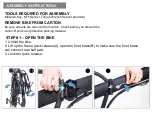
Page 7: ...rotective packing material TOOLS REQUIRED FOR ASSEMBLY M6 Allen Key M15 Spnner Torque Wrench Set not provided ASSEMBLY INSTRUCTIONS STEP 1 OPEN THE BIKE 1 Unfold the bike 2 Lift up the frame quick rel...

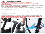
Page 8: ...rying to turn the handlebar If you can turn the handlebar without turning the front wheel the stem is too loose Adjust the handlebar angle which is perpendicular to front wheel Retighten the stem pill...

Page 9: ...spindle 2 Thread the pedal marked R into the crank arm on the chain side of the bike Turn the pedal spindle in a clockwise direction Securely tighten the pedal spindle by M15 tool 3 Thread the pedal...

Page 10: ...t top of seat is parallel the ground and comfortable to the rider Retighten seat clamp nuts securely with an adjustable wrench NOTE Especially pay attention to the insertion warning mark NOTE Test the...

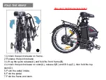
Page 11: ...A B A C B D FOLD THE EBIKE...

Page 12: ...ick release 3 Lift up the quick release A and fold the front frame B 4 Unlock the quick release on stem A release it B and lift it up C then fold the top stem D 5 Push the pedal inside 6 Fold the peda...

Page 13: ...ts to the front of the Bicycle See illustration A 2 Insert the wheel into the fork 3 Install an axle nut to each side of the axle see illustration B 4 Tighten the axle nuts by hand Make sure there is...

Page 14: ...a 6 mm hex key You may hand tighten at this point as you will need to readjust the tension later See illustration A 2 Install the inner brake cable by pushing it through the cable routing tube or noo...

Page 15: ...brake arms must be nearly parallel to each other To make this adjustment hold the brake shoes so that they are touching the rim and measure the distance between points a and b See illustration C 4 Adj...

Page 16: ...n will be100 charged and the charger will automatically stop charging From 0 charge to 100 takes about 5 hours 5 Press the button on the battery the LED light will be illuminated to show battery perce...

Page 17: ...uent use or storage recharge the battery at least every month to ensure that it will work properly and keep in a dry and cool environment OPERATION SEE PICTURE ATTACHED AS BELOW 1 START Insert the key...

Page 18: ......
Page 19: ...Pty Ltd to change the fuse The travelling distance has been reduced Insufficient battery capacity The battery is becoming old and needs replacement Braking frequently riding uphill or running against...

Page 20: ...pinning the pedals backwards The chain needs to be as tight as possible without creating friction that will waste energy and wear the chain and cogs prematurely Professionals are required to operate t...

Page 21: ...ecautions will void the warranty The commercial warranty is strictly limited to the replacement and or repair of the parts recognized as defective Do not open the battery the motor wheel the watertigh...

Page 22: ...to have the goods repaired or replaced if the goods fail to be of acceptable quality and the failure does not amount to a major failure Full details of your consumer rights may be found at www consum...

Reviews: