11
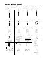
PARTS REQUIRED
q
{1} Left Wing Half w/Aileron & Hinges
q
{1} Right Wing Half w/Aileron & Hinges
q
{2} Plywood Dihedral Brace
2
3
13
TOOLS AND SUPPLIES REQUIRED
q
Kwik Bond 30 Minute Epoxy
q
Excel Modeling Knife
q
12” Straight Edge Ruler
q
Masking Tape
q
220 Grit Sandpaper w/Sanding Block
q
Pen or Pencil
q
Paper Towels
q
Rubbing Alcohol
q
NHP Epoxy Mixing Sticks
q
NHP Epoxy Mixing Cups
3
The covering material used on the Right Flyer 60H
is a heat shrink polyester material. Because of this, it
is possible that with heat and humidity changes the
covering on your airplane may wrinkle or sag. This
trait is inherent in all types of heat shrink covering
material. To remove the wrinkles you will need to
purchase, or borrow from a fellow modeler, a heat iron.
If you need to purchase one, the Global Heat Sealing
Iron # 360900 is recommended.
Follow these simple steps to remove the wrinkles:
q
1) Plug in and turn on the sealing iron to the
medium temperature setting. Allow the iron to heat
up for approximately 5 - 7 minutes.
q
2) After the iron has reached temperature,
lightly apply the iron to the wrinkled section of
the covering. Move the iron slowly over the
wrinkled section until the covering tightens and the
wrinkles disappear. You will notice that the color
of the covering will darken when it is heated. When
the covering cools back down, it will return to its
normal color.
A NOTE ABOUT COVERING
WING ASSEMBLY
INSTALLING THE DIHEDRAL BRACE
7
15
18
19
20
22
q
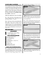
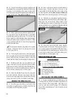
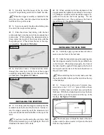
1) Look carefully at the surface of each root rib
on both wing halves. Notice how the excess cover-
ing material overlaps onto them. Using a modeling
knife, carefully trim and remove the excess from both
of the root ribs, leaving about 1/16” of
Photo # 1
covering material overlapping so it does not pull
away later. See photo # 1 below.
?
Removing most of the covering from the two
root ribs will expose more of the wood. This will
result in a stronger joint when the wing halves are
epoxied together later.
q
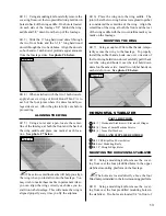
2) Using a straight edge ruler and a pen, locate
and mark the centerline of the plywood dihedral brace.
Draw one vertical line, on each side of the brace, at
this location. See photo # 2 below.
23
24
Photo # 2
q
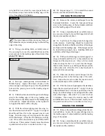
3) Test fit the plywood dihedral brace into the
plywood dihedral brace box in each wing half. The
brace should slide into each wing half up to its cen-
terline. If it does not, remove the brace and lightly
sand the edges and tips until the proper fit is obtained.
See photo # 3 below.
25
Photo # 3
?
The dihedral brace is cut in the shape of a "V".
The "V" shape should face the top surface of the wing
when the brace is installed.


