15
q
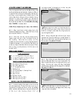
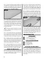
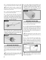
5) Remove the vertical stabilizer. Using a
modeling knife, carefully remove the covering from
below the lines you drew. Also remove the cover-
ing from the bottom edge of the stabilizer and from
inside the outline you drew on top of the fuselage.
See photo # 12 below.
Photo # 12
?
When cutting through the covering material to
remove it, cut with only enough pressure to only cut
through the covering itself. Cutting down into the
balsa may weaken the structure.
q
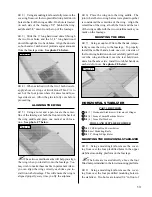
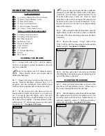
6) Set the vertical stabilizer back into place and
realign it. Now, using a builder's triangle, check to
ensure that the vertical stabilizer is aligned 90º to the
horizontal stabilizer. See figure # 2 below.
Figure # 2
q
7) Once you are satisfied that the vertical stabi-
lizer is aligned correctly, mix up a generous amount
of Kwik Bond 30 Minute Epoxy. Apply a thin layer
to the mounting slot in the fuselage and to the sides
and bottom of the vertical stabilizer. Also, apply a
thin layer of epoxy to the top of the fuselage.
q
8) Set the vertical stabilizer into place and re-
align it. Hold the stabilizer in place with masking
tape and double check all of your measurements once
more before the epoxy cures. Remove any excess
epoxy using a paper towel and rubbing alcohol.
Allow the epoxy to fully cure before proceeding.
MOUNTING THE VERTICAL STABILIZER
TOOLS AND SUPPLIES REQUIRED
q
Kwik Bond Thin C/A
q
Kwik Bond 30 Minute Epoxy
q
Excel Modeling Knife
q
Scissors
q
Waxed Paper
q
NHP Epoxy Mixing Sticks
q
NHP Epoxy Mixing Cups
1
CONTROL SURFACE HINGING
HINGING THE AILERONS
3
7
16
17
24
q
1) Remove the ailerons and hinges from the
wing. Locate the four precut hinge slots in the trail-
ing edge of each half of the wing and the leading
edge of each aileron.
q
2) Using a modeling knife, carefully remove any
excess covering from over each of the hinge slots in
the ailerons and the wing.
q
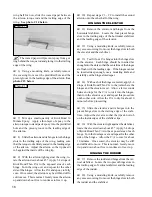
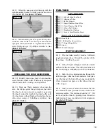
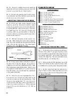
3) Test fit four C/A hinges into the hinge slots
in one aileron. Each hinge should be inserted far
enough into the slots so that the centerline of the
hinges are flush with the leading edge of the aileron.
If the hinges cannot be inserted deeply enough, use a
modeling knife and carefully cut the hinge slots
deeper. See photo # 13 below.
Photo # 13
q
4) With each of the hinges centered in the hinge
slots, apply 3-4 drops of Kwik Bond Thin C/A to the
joint where the hinges and the ailerons meet. Allow
a few seconds between drops for the C/A to wick
into the hinges, then turn the aileron over and repeat
this procedure on the other side of each hinge. Al-
low the C/A to dry for about 10 minutes before
proceeding.
q
5) Using a pair of scissors, cut out a 1-1/2” x
2-1/4” piece of waxed paper. Working with one
25
90º


