12
INSTALLING THE WING FAIRING
q
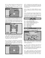
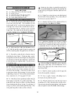
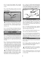
10) Using a modeling knife, or Lexan Canopy
Scissors, cut out the plastic wing fairing along the
molded scribe line. See photo # 18 below.
Photo # 18
q
11) Test fit the fairing to the bottom of the wing.
There should be about 1/16” gap between the front
edge of the fairing and the back edge of the fuselage.
q
12) Using a modeling knife, carefully trim the
forward edges of the fairing to match the contour of
the wing's leading edge.
q
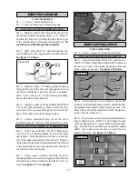
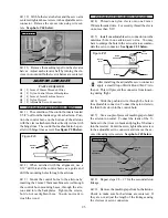
13) When satisfied with the fit, glue the fairing
to the wing using RC256 Canopy Glue. Use pieces
of masking tape to hold the fairing in place until the
glue completely cures. See photo # 19 below.
Photo # 19
PARTS REQUIRED
q
{1} Horizontal Stabilizer with Elevator Halves
q
{6} C/A Hinges
HORIZONTAL STABILIZER
INSTALLATION
ALIGNING THE HORIZONTAL STABILIZER
q
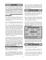
1) Using a ruler and a pen, locate the centerline
of the horizontal stabilizer, at the trailing edge, and
place a mark. Use a triangle and extend this mark,
from back to front, across the top of the stabilizer.
q
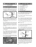
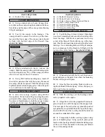
2) Slide the stabilizer into place in the precut
slot in the rear of the fuselage. To center the stabi-
lizer from side to side, measure the stabilizer from
the fuselage sides out to the stabilizer's tips. Both
measurements should be equal when the stabilizer is
centered. See figure # 8 below.
Figure # 8
q
3) When satisfied that the stabilizer is centered,
place a mark on each side of the top and bottom of
the stabilizer where it and the fuselage sides meet.
Doing this will help you realign the stabilizer later.
q
4) With the stabilizer centered in the fuselage,
use a couple of pieces of masking tape or a T-pin to
secure the stabilizer in place at the trailing edge only.
q
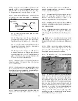
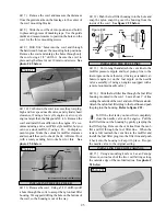
5) Align the stabilizer to the wing. When viewed
from the rear, the stabilizer should be level with the
wing. If it is not, remove the stabilizer and use 220 grit
sandpaper to sand down the high side of the stabilizer
mounting platform in the fuselage until the stabilizer is
level with the wing. Measure the distance from each
wing tip to each stabilizer tip. These distances should
be equal. See figures # 9 and # 10 below.
Figure # 9
q
6) When you are satisfied with the alignment,
hold the stabilizer in place using a couple of pieces of
masking tape or a couple of T-pins.
Figure # 10
Wing
Fairing
Leave 1/8”
Material
Wing
Fairing
Bottom
Surfaces
Flush
A
A-1
A = A-1
B
B-1
B = B-1
C
C-1
C = C-1
1/16” Gap


