17
q
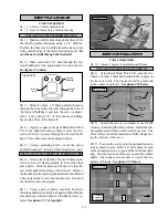
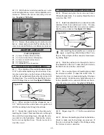
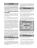
15) With your engine still installed on the mo-
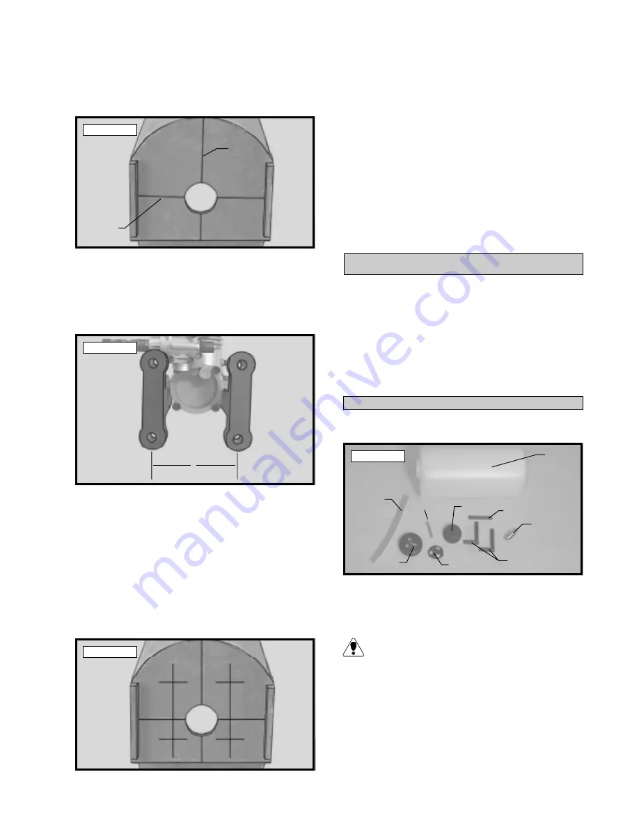
tor mount beams, use a ruler and measure the width
between the predrilled mounting holes in the motor
mount. This distance will vary depending on the
brand and size of the engine you have chosen. See
photo # 32 below.
q
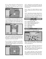
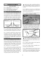
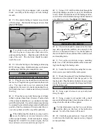
14) Using a ruler and a pen, measure up from
the bottom of the firewall 1-1/2” and place two
marks. Draw a horizontal line at these two marks.
See photo # 31 below.
Photo # 31
q
16) Divide the measurement found in step # 15
in half. Measure and mark this resulting distanceand
place marks to the right and left of the vertical center-
line. Draw one vertical line at the marks made to the
right and left of the vertical centerline.
q
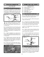
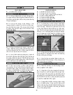
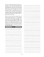
17) On the two vertical lines you just drew,
measure and place two marks 5/8” below the hori-
zontal centerline and two marks 1-1/16” above the
horizontal centerline (looking at the firewall). See
photo # 33 below.
Photo # 32
q
18) Hold the motor mount assembly up to the
firewall and double check that the four intersecting
lines line up with the four predrilled holes in the mo-
tor mount beams.
q
19) Using a 7/32” drill bit, drill the four mount-
ing holes through the firewall for the motor mount
beams.
q
20) Mount the motor mount assembly to the fire-
wall using the four 4mm x 20mm machine screws,
four 4mm flat washers and four 4mm blind nuts.
Tighten the screws securely to draw the blind nuts
into the back of the firewall completely.
Photo # 33
PARTS REQUIRED
q
{1} 280cc Molded Fuel Tank
q
{1} 4mm x 28mm Nylon Pick-Up Tube
q
{2} 4mm x 28mm Prebent Nylon Vent Tube
q
{1} 3mm x 18mm Self Tapping Screw
q
{1} Length of Fuel Tubing
q
{1} Metal Weighted Pick-Up
q
{1) Nylon Fuel Cap
q
{1} Rubber Stopper
q
{1} Nylon Backplate
FUEL TANK
STOPPER ASSEMBLY
q
2) Using a modeling knife, cut the silicon fuel
tubing to 3-3/4” long. Connect one end of the tubing
to the weighted pick-up.
There are three molded holes in the rubber fuel
tank stopper. Two are opened and one is cov-
ered by a thin layer of rubber on the front of the stop-
per. Using a modeling knife, remove the thin layer of
rubber to completely open the third hole.
q
3) Push the single 4mm x 28mm nylon pickup
tube through one hole in the rubber stopper until 3/8”
protrudes from the front of the stopper. Slide the ny-
lon backplate over the tube at the back of the stopper.
q
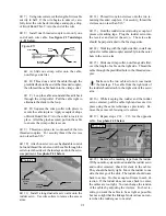
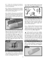
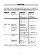
1) Identify each of the parts that make up the
fuel tank assembly. See photo # 34 below.
Photo # 34
Vertical
Centerline
Horizontal
Centerline
Tank
Clunk
Silicon
Tube
Rubber
Stopper
Backplate
Screw
Pickup
Tube
Vent
Tubes
Cap
X
X = Distance
Between Beam
Mounting Holes


