21
q
7) Using wire cutters, cut the length of wire cable
exactly in half. If the wire begins to unravel, care-
fully twist the wire back into shape and apply a drop
of Kwik Bond Thin C/A to the end of the wire.
q
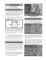
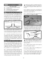
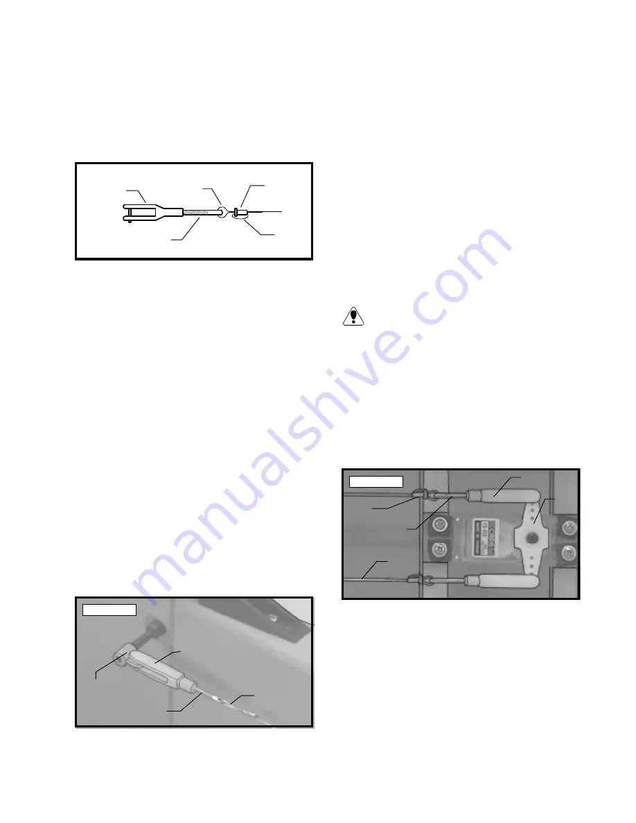
8) Install one threaded coupler onto only one
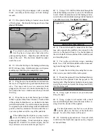
end of each wire cable. See figure # 17 and steps
A - D below.
Figure # 17
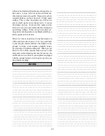
q
A) Slide one crimp collet onto the cable,
non-flange side first.
q
B) Thread one end of the cable through the
predrilled hole in the end of the threaded coupler,
then thread the cable back into the crimp collet.
q
C) Loop the cable around and thread it back
through the crimp collet. Pull the cable tight to
eliminate the slack in the loop.
q
D) Squeeze the crimp collet with pliers to
secure the cable in place. Apply a couple of drops
of Kwik Bond Thin C/A to the collet to lock it in
place. After the glue has cured, pull on the cable
to ensure the crimp collet is secure.
q
9) Thread one nylon clevis onto each of the two
threaded couplers. For security thread the clevises
on no less than 5/16”.
q
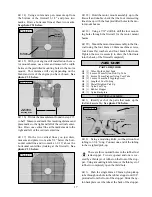
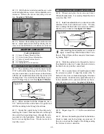
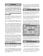
10) Attach one clevis to each adjustable control
horn and thread the other end of the cable through the
exit slots in the sides of the fuselage and into the servo
compartment. See photo # 41 below.
Photo # 41
q
12) Thread two nylon clevises onto the two re-
maining threaded couplers. For security, thread the
clevises on no less than 5/16”.
q
13) Hold the rudder in neutral using a couple of
pieces of masking tape. Plug the rudder servo into
the receiver and center the servo. The servo arm
should be perpendicular to the fuselage sides.
q
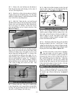
14) Working with the right side first, install one
nylon clevis/threaded coupler assembly into the outer
hole in the servo arm.
q
15) Slide one crimp collet, non-flange side first,
over the length of cable on the right side. Thread the
cable through the predrilled hole in the threaded cou-
pler.
Make sure the two cables do not cross inside
the fuselage. The cable from the right side of
the rudder should attach to the right side of the servo
arm.
q
16) While keeping the rudder and the rudder
servo centered, pull the cable tight and secure it in
place using the same technique as previously. Re-
move the excess cable using wire cutters.
q
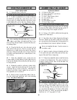
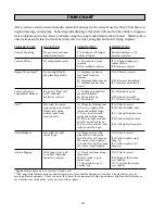
17) Repeat steps # 14 - # 16 for the opposite
cable. See photo # 42 below.
Photo # 42
q
18) Remove the masking tape from the rudder.
With you radio system turned on and the rudder servo
and rudder centered, check for slack in the cables.
They should be fairly tight. Move the rudder to one
side, then let go of the stick. The rudder should come
back to center. Do this a couple of times in each di-
rection. If the rudder does not come back to center,
the cables are too tight. You can change the tension
of the cables by adjusting the clevises. For best re-
sults, you want the cables to be as tight as possible,
but not so tight that the linkage binds or does not cen-
ter when the rudder goes to neutral.
q
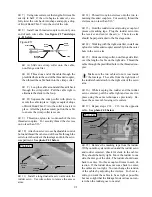
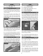
11) Install a long dual-arm servo arm onto the
rudder servo. Use wire cutters to remove the excess
arms.
Clevis
Threaded
Coupler
Wire
Cable
Crimp
Collet
Loop
Adjustable
Control
Horn
Clevis
Threaded
Coupler
Cable
Cable
Clevis
Servo
Arm
Threaded
Coupler
Crimp
Collet


